Up to date
This page is up to date for Godot 4.2.
If you still find outdated information, please open an issue.
2Dカスタム描画
はじめに
Godot has nodes to draw sprites, polygons, particles, and all sorts of stuff. For most cases, this is enough. If there's no node to draw something specific you need, you can make any 2D node (for example, Control or Node2D based) draw custom commands.
Custom drawing in a 2D node is really useful. Here are some use cases:
Drawing shapes or logic that existing nodes can't do, such as an image with trails or a special animated polygon.
ノードと互換性のない視覚化、例えばテトリスボード等。 (テトリスの例では、カスタム描画関数を使用してブロックを描画します。)
Drawing a large number of simple objects. Custom drawing avoids the overhead of using a large number of nodes, possibly lowering memory usage and improving performance.
Making a custom UI control. There are plenty of controls available, but when you have unusual needs, you will likely need a custom control.
描画
Control や Node2D のような CanvasItem から派生したノードにスクリプトを追加します。次に _draw() 関数をオーバーライドします。
extends Node2D

func _draw():
    # Your draw commands here
    pass
public override void _Draw()
{
    // Your draw commands here
}
描画のコマンドについては、 CanvasItem クラスリファレンスを参照してください。たくさんあります。
描画の更新
_draw() 関数は一度だけ呼び出され、その後は描画コマンドがキャッシュされて記憶されるため、それ以上の呼び出しは不要です。
If re-drawing is required because a state or something else changed,
call CanvasItem.queue_redraw()
in that same node and a new _draw() call will happen.
次に、もう少し複雑な例を示します。テクスチャ変数を変更すると再描画されます:
extends Node2D

@export var texture: Texture:
        set = _set_texture

func _set_texture(value):
    # If the texture variable is modified externally,
    # this callback is called.
    texture = value  # Texture was changed.
    queue_redraw()  # Trigger a redraw of the node.

func _draw():
    draw_texture(texture, Vector2())
using Godot;

public partial class MyNode2D : Node2D
{
    private Texture _texture;
    public Texture Texture
    {
        get
        {
            return _texture;
        }

        set
        {
            _texture = value;
            QueueRedraw();
        }
    }

    public override void _Draw()
    {
        DrawTexture(_texture, new Vector2());
    }
}
In some cases, it may be desired to draw every frame. For this,
call queue_redraw() from the _process() callback, like this:
extends Node2D

func _draw():
    # Your draw commands here
    pass

func _process(delta):
    queue_redraw()
using Godot;

public partial class CustomNode2D : Node2D
{
    public override void _Draw()
    {
        // Your draw commands here
    }

    public override void _Process(double delta)
    {
        QueueRedraw();
    }
}
座標
The drawing API uses the CanvasItem's coordinate system, not necessarily pixel coordinates. Which means it uses the coordinate space created after applying the CanvasItem's transform. Additionally, you can apply a custom transform on top of it by using draw_set_transform or draw_set_transform_matrix.
When using draw_line, you should consider the width of the line.
When using a width that is an odd size, the position should be shifted
by 0.5 to keep the line centered as shown below.
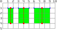
func _draw():
    draw_line(Vector2(1.5, 1.0), Vector2(1.5, 4.0), Color.GREEN, 1.0)
    draw_line(Vector2(4.0, 1.0), Vector2(4.0, 4.0), Color.GREEN, 2.0)
    draw_line(Vector2(7.5, 1.0), Vector2(7.5, 4.0), Color.GREEN, 3.0)
public override void _Draw()
{
    DrawLine(new Vector2(1.5f, 1.0f), new Vector2(1.5f, 4.0f), Colors.Green, 1.0f);
    DrawLine(new Vector2(4.0f, 1.0f), new Vector2(4.0f, 4.0f), Colors.Green, 2.0f);
    DrawLine(new Vector2(7.5f, 1.0f), new Vector2(7.5f, 4.0f), Colors.Green, 3.0f);
}
The same applies to the draw_rect method with filled = false.
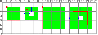
func _draw():
    draw_rect(Rect2(1.0, 1.0, 3.0, 3.0), Color.GREEN)
    draw_rect(Rect2(5.5, 1.5, 2.0, 2.0), Color.GREEN, false, 1.0)
    draw_rect(Rect2(9.0, 1.0, 5.0, 5.0), Color.GREEN)
    draw_rect(Rect2(16.0, 2.0, 3.0, 3.0), Color.GREEN, false, 2.0)
public override void _Draw()
{
    DrawRect(new Rect2(1.0f, 1.0f, 3.0f, 3.0f), Colors.Green);
    DrawRect(new Rect2(5.5f, 1.5f, 2.0f, 2.0f), Colors.Green, false, 1.0f);
    DrawRect(new Rect2(9.0f, 1.0f, 5.0f, 5.0f), Colors.Green);
    DrawRect(new Rect2(16.0f, 2.0f, 3.0f, 3.0f), Colors.Green, false, 2.0f);
}
例:円弧の描画
次に、Godotエンジンのカスタム描画機能を使用して、Godotが機能を提供しないものを描画します。たとえば、Godotには円全体を描画する draw_circle() 関数が用意されています。しかし、円の一部を描くのはどうでしょうか?自分でこれを実行して描画をするには、関数をコーディングする必要があります。
Arc関数
円弧は、サポート円パラメーター、つまり中心位置と半径によって定義されます。円弧自体は、開始角度と停止角度によって定義されます。これらは、描画関数に提供する必要がある4つの引数です。また、色の値も提供するため、必要に応じて異なる色で弧を描くことができます。
Basically, drawing a shape on the screen requires it to be decomposed into a certain number of points linked from one to the next. As you can imagine, the more points your shape is made of, the smoother it will appear, but the heavier it will also be in terms of processing cost. In general, if your shape is huge (or in 3D, close to the camera), it will require more points to be drawn without it being angular-looking. On the contrary, if your shape is small (or in 3D, far from the camera), you may decrease its number of points to save processing costs; this is known as Level of Detail (LOD). In our example, we will simply use a fixed number of points, no matter the radius.
func draw_circle_arc(center, radius, angle_from, angle_to, color):
    var nb_points = 32
    var points_arc = PackedVector2Array()

    for i in range(nb_points + 1):
        var angle_point = deg_to_rad(angle_from + i * (angle_to-angle_from) / nb_points - 90)
        points_arc.push_back(center + Vector2(cos(angle_point), sin(angle_point)) * radius)

    for index_point in range(nb_points):
        draw_line(points_arc[index_point], points_arc[index_point + 1], color)
public void DrawCircleArc(Vector2 center, float radius, float angleFrom, float angleTo, Color color)
{
    int nbPoints = 32;
    var pointsArc = new Vector2[nbPoints + 1];

    for (int i = 0; i <= nbPoints; i++)
    {
        float anglePoint = Mathf.DegToRad(angleFrom + i * (angleTo - angleFrom) / nbPoints - 90f);
        pointsArc[i] = center + new Vector2(Mathf.Cos(anglePoint), Mathf.Sin(anglePoint)) * radius;
    }

    for (int i = 0; i < nbPoints - 1; i++)
    {
        DrawLine(pointsArc[i], pointsArc[i + 1], color);
    }
}
Remember the number of points our shape has to be decomposed into? We fixed this
number in the nb_points variable to a value of 32. Then, we initialize an empty
PackedVector2Array, which is simply an array of Vector2s.
次のステップでは、円弧を構成する32個の点の実際の位置を計算します。これは最初のforループで行われ、位置を計算したいポイントの数に最後のポイントを含めるために1を加えて繰り返します。最初に、開始角度と終了角度の間の各点の角度を決定します。
The reason why each angle is decreased by 90° is that we will compute 2D positions
out of each angle using trigonometry (you know, cosine and sine stuff...). However,
cos() and sin() use radians, not degrees. The angle of 0° (0 radian)
starts at 3 o'clock, although we want to start counting at 12 o'clock. So we decrease
each angle by 90° in order to start counting from 12 o'clock.
The actual position of a point located on a circle at angle angle (in radians)
is given by Vector2(cos(angle), sin(angle)). Since cos() and sin() return values
between -1 and 1, the position is located on a circle of radius 1. To have this
position on our support circle, which has a radius of radius, we simply need to
multiply the position by radius. Finally, we need to position our support circle
at the center position, which is performed by adding it to our Vector2 value.
Finally, we insert the point in the PackedVector2Array which was previously defined.
次に、実際にポイントを描画する必要があります。ご想像のとおり、単純に32ポイントを描画するのではなく、それぞれの間にあるすべてのものを描画する必要があります。前の方法を使用してすべてのポイントを自分で計算し、それを1つずつ描画することもできます。しかし、これはあまりに複雑で非効率的であるため(明示的に必要な場合を除く)、各ポイントのペア間に単純に線を引きます。サポート円の半径が大きくない限り、1組のポイント間の各線の長さは、それらが個々の直線として見えてしまう長さになることはありません。もしもその場合は、ポイント数を増やすだけで済みます。
画面上に円弧を描画する
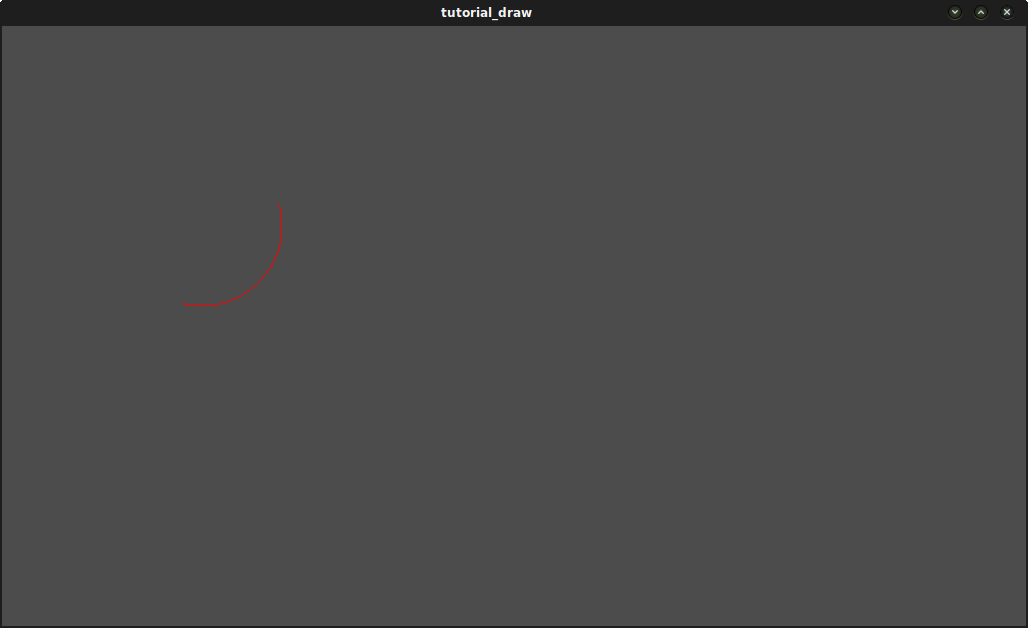
これで、画面上に物を描画する関数ができました。_draw() 関数内で呼び出します:
func _draw():
    var center = Vector2(200, 200)
    var radius = 80
    var angle_from = 75
    var angle_to = 195
    var color = Color(1.0, 0.0, 0.0)
    draw_circle_arc(center, radius, angle_from, angle_to, color)
public override void _Draw()
{
    var center = new Vector2(200, 200);
    float radius = 80;
    float angleFrom = 75;
    float angleTo = 195;
    var color = new Color(1, 0, 0);
    DrawCircleArc(center, radius, angleFrom, angleTo, color);
}
結果:
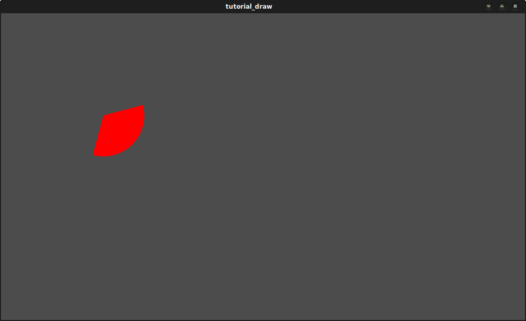
Arc polygon関数
これをさらに一歩進めて、円弧で定義されたディスクのプレーン部分だけでなく、その形状を描画する関数を作成することもできます。この処理は、線の代わりに多角形を描くことを除いて、以前とまったく同じです:
func draw_circle_arc_poly(center, radius, angle_from, angle_to, color):
    var nb_points = 32
    var points_arc = PackedVector2Array()
    points_arc.push_back(center)
    var colors = PackedColorArray([color])

    for i in range(nb_points + 1):
        var angle_point = deg_to_rad(angle_from + i * (angle_to - angle_from) / nb_points - 90)
        points_arc.push_back(center + Vector2(cos(angle_point), sin(angle_point)) * radius)
    draw_polygon(points_arc, colors)
public void DrawCircleArcPoly(Vector2 center, float radius, float angleFrom, float angleTo, Color color)
{
    int nbPoints = 32;
    var pointsArc = new Vector2[nbPoints + 2];
    pointsArc[0] = center;
    var colors = new Color[] { color };

    for (int i = 0; i <= nbPoints; i++)
    {
        float anglePoint = Mathf.DegToRad(angleFrom + i * (angleTo - angleFrom) / nbPoints - 90);
        pointsArc[i + 1] = center + new Vector2(Mathf.Cos(anglePoint), Mathf.Sin(anglePoint)) * radius;
    }

    DrawPolygon(pointsArc, colors);
}
動的カスタム描画
さて、私たちは今、画面上にカスタムのものを描画できるようになりました。ただし、動きません。そこで、この図形を中心で回してみましょう。これを行うための解決策は、単にangle_fromとangle_toの値を経時的に変更させることです。この例では、単純に50ずつインクリメントします。このインクリメント値は一定のままにする必要があります。そうしないと、それに応じて回転速度が変化します。
まず、スクリプトの先頭で、angle_from変数とangle_to変数の両方をグローバルにする必要があります。また、他のノードに保存し、get_node() を使用してアクセスすることもできます。
extends Node2D

var rotation_angle = 50
var angle_from = 75
var angle_to = 195
using Godot;

public partial class MyNode2D : Node2D
{
    private float _rotationAngle = 50;
    private float _angleFrom = 75;
    private float _angleTo = 195;
}
これらの値は_process(delta)関数で変更します。
ここではangle_fromとangle_to値をインクリメントします。ただし、0から360°の間に結果の値を wrap() することを忘れてはなりません。つまり、角度が361°の場合、実際には1°です。これらの値をラップしない場合、スクリプトは当面は正しく動作しますが、Godot が管理できる最大整数値 (2^31 - 1)に達するまで、角度の値は時間の経過と共に大きくなります。この現象を放置すると、Godotがクラッシュしたり、予期しない動作が発生する可能性があります。
Finally, we must not forget to call the queue_redraw() function, which automatically
calls _draw(). This way, you can control when you want to refresh the frame.
func _process(delta):
    angle_from += rotation_angle
    angle_to += rotation_angle

    # We only wrap angles when both of them are bigger than 360.
    if angle_from > 360 and angle_to > 360:
        angle_from = wrapf(angle_from, 0, 360)
        angle_to = wrapf(angle_to, 0, 360)
    queue_redraw()
public override void _Process(double delta)
{
    _angleFrom += _rotationAngle;
    _angleTo += _rotationAngle;

    // We only wrap angles when both of them are bigger than 360.
    if (_angleFrom > 360 && _angleTo > 360)
    {
        _angleFrom = Mathf.Wrap(_angleFrom, 0, 360);
        _angleTo = Mathf.Wrap(_angleTo, 0, 360);
    }
    QueueRedraw();
}
また、これらの変数を利用するために _draw() 関数を変更することを忘れないでください:
func _draw():
   var center = Vector2(200, 200)
   var radius = 80
   var color = Color(1.0, 0.0, 0.0)

   draw_circle_arc( center, radius, angle_from, angle_to, color )
public override void _Draw()
{
    var center = new Vector2(200, 200);
    float radius = 80;
    var color = new Color(1, 0, 0);

    DrawCircleArc(center, radius, _angleFrom, _angleTo, color);
}
実行しましょう!動作はしますが、アークがものすごい速さで回転しています!何故でしょうか?
その理由は、GPUが実際にできるだけ速くフレームを表示しているからです。この速度で図面を「正規化」する必要があります。そのためには、_process() 関数の delta パラメーターを利用する必要があります。delta には、最後にレンダリングされた2つのフレーム間の経過時間が含まれます。通常は小さい(約0.0003秒ですが、これはハードウェアによって異なります)ため、delta を使用して描画を制御すると、プログラムがすべてのハードウェアで同じ速度で実行されます。
この場合、単に _process() 関数で rotation_angle 変数に delta を乗算するだけです。このように、2つの角度は、レンダリング速度に直接依存する非常に小さな値で増加します。
func _process(delta):
    angle_from += rotation_angle * delta
    angle_to += rotation_angle * delta

    # We only wrap angles when both of them are bigger than 360.
    if angle_from > 360 and angle_to > 360:
        angle_from = wrapf(angle_from, 0, 360)
        angle_to = wrapf(angle_to, 0, 360)
    queue_redraw()
public override void _Process(double delta)
{
    _angleFrom += _rotationAngle * (float)delta;
    _angleTo += _rotationAngle * (float)delta;

    // We only wrap angles when both of them are bigger than 360.
    if (_angleFrom > 360 && _angleTo > 360)
    {
        _angleFrom = Wrap(_angleFrom, 0, 360);
        _angleTo = Wrap(_angleTo, 0, 360);
    }
    QueueRedraw();
}
もう一度実行しましょう!今度は、回転が正常に表示されます!
Antialiased drawing
Godot offers method parameters in draw_line
to enable antialiasing, but not all custom drawing methods offer this antialiased
parameter.
For custom drawing methods that don't provide an antialiased parameter,
you can enable 2D MSAA instead, which affects rendering in the entire viewport.
This provides high-quality antialiasing, but a higher performance cost and only
on specific elements. See 2D antialiasing for more information.
ツール
Drawing your own nodes might also be desired while running them in the editor. This can be used as a preview or visualization of some feature or behavior. See エディタでコードを実行する for more information.