Mesh generation with heightmap and shaders
Introduction
This tutorial will help you to use Godot shaders to deform a plane mesh so it appears like a basic terrain. Remember that this solution has pros and cons.
Pros:
- Pretty easy to do.
- This approach allows computation of LOD terrains.
- The heightmap can be used in Godot to create a normal map.
Cons:
- The Vertex Shader can’t re-compute normals of the faces. Thus, if your mesh is not static, this method will not work with shaded materials.
- This tutorial uses a plane mesh imported from Blender to Godot Engine. Godot is able to create meshes as well.
See this tutorial as an introduction, not a method that you should employ in your games, except if you intend to do LOD. Otherwise, this is probably not the best way.
However, let’s first create a heightmap,or a 2D representation of the terrain. To do this, I’ll use GIMP, but you can use any image editor you like.
The heightmap
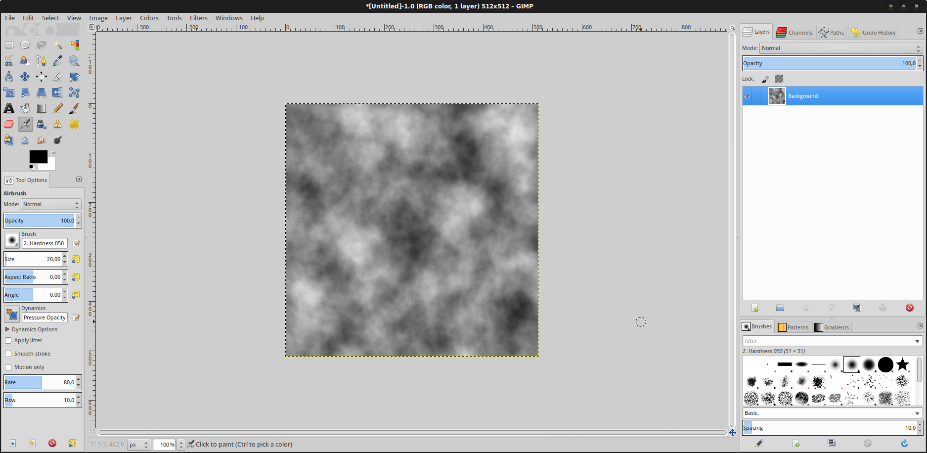
We will use a few functions of GIMP image editor to produce a simple heightmap. Start GIMP and create a square image of 512x512 pixels.
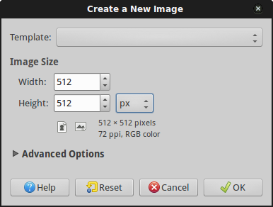
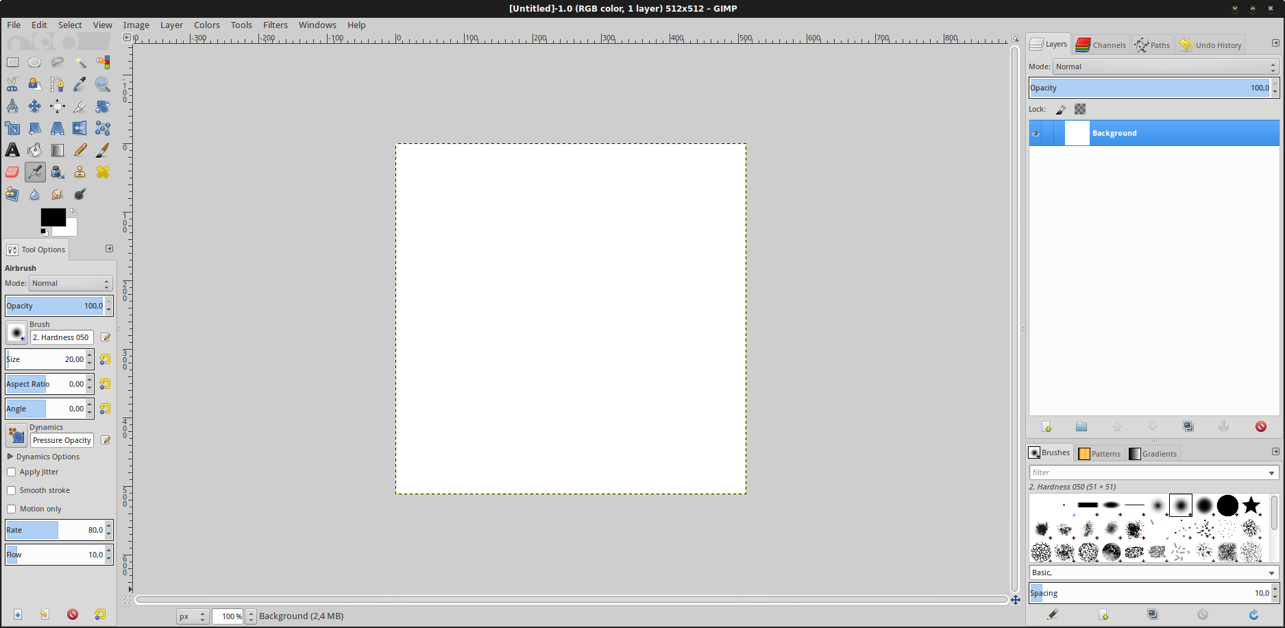
You are now in front of a new, blank, square image.
Then, use a filter to render some clouds on this new image.
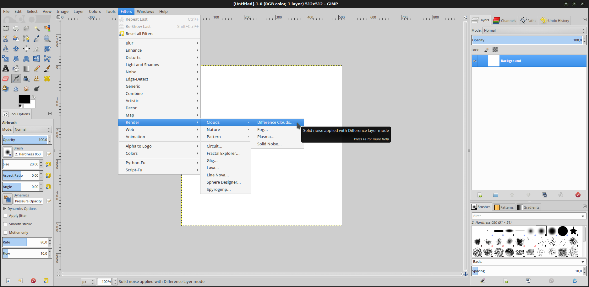
Parameter this filter to whatever you want. A white pixel corresponds to the highest point of the heightmap, a black pixel corresponds to the lowest one. So, darker regions are valleys and brighter are mountains. If you want, you can check “tileable” to render a heightmap that can be cloned and tiled close together with another one. X and Y size don’t matter a lot as long as they are big enough to provide a decent ground. A value of 4.0 or 5.0 for both is nice. Click on the “New Seed” button to roll a dice and GIMP will create a new random heightmap. Once you are happy with the result, click “OK”.
You can continue to edit your image if you wish. For our example, let’s keep the heightmap as is, and let’s export it to a PNG file, say “heightmap.png”. Save it in your Godot project folder.
The plane mesh
Now, we will need a plane mesh to import in Godot. Let’s run Blender.
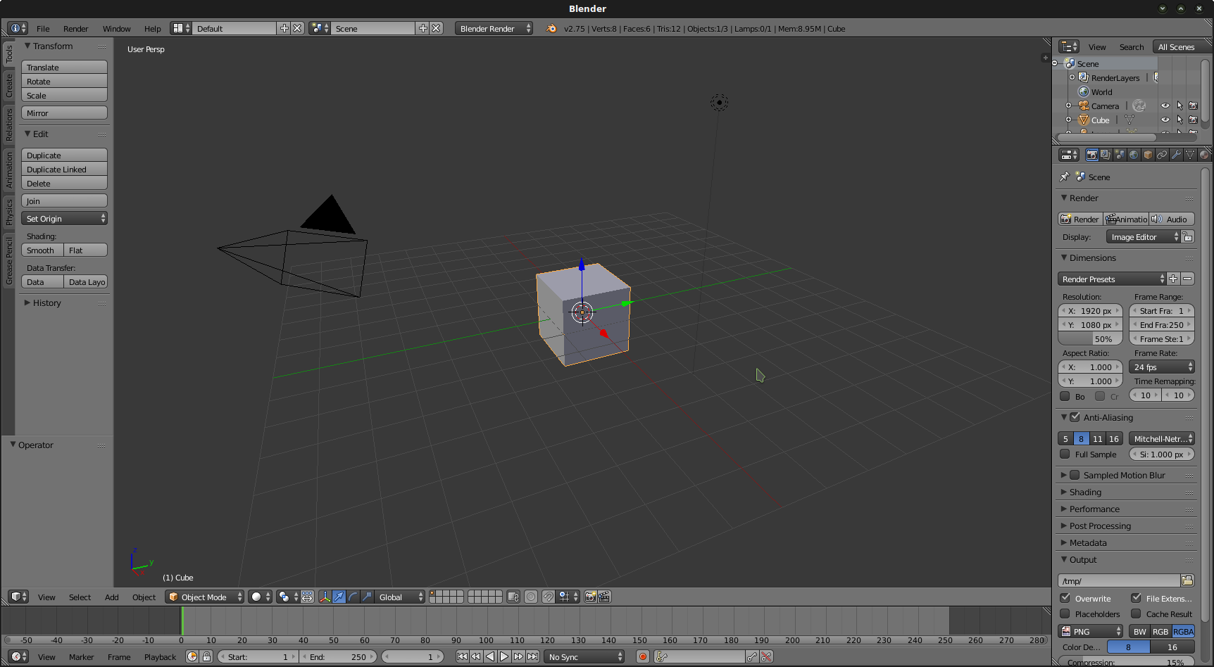
Remove the start cube mesh, then add a new plane to the scene.
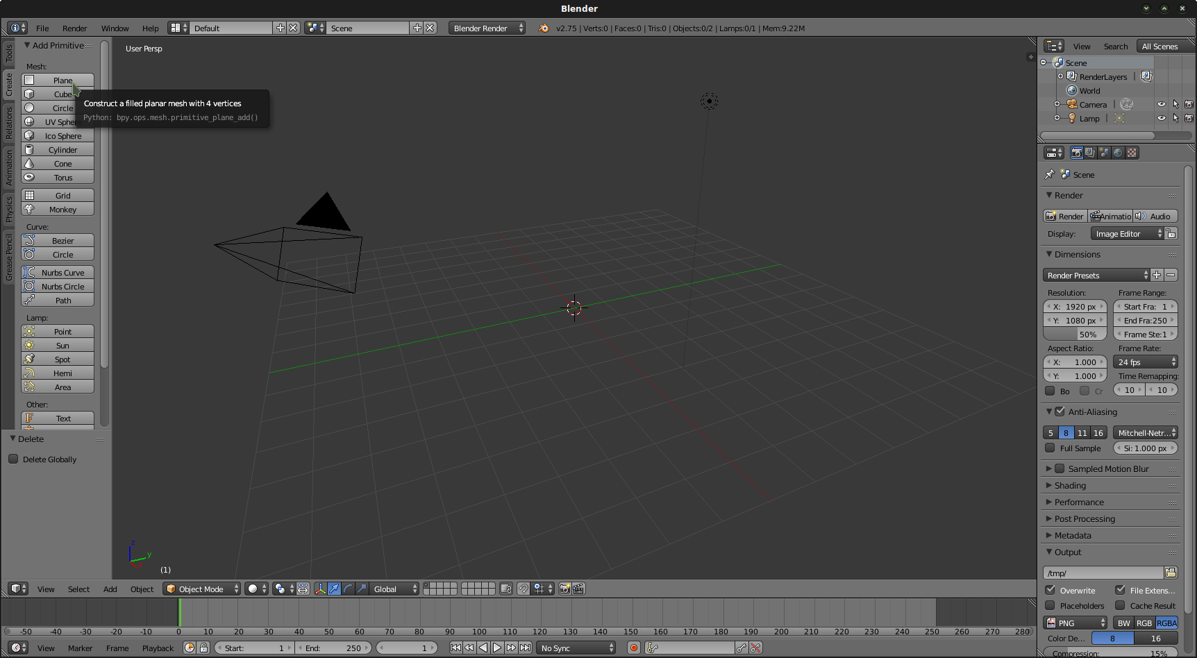
Zoom a bit, then switch to Edit mode (Tab key) and in the Tools buttongroup at the left, hit “Subdivide” 5 or 6 times.
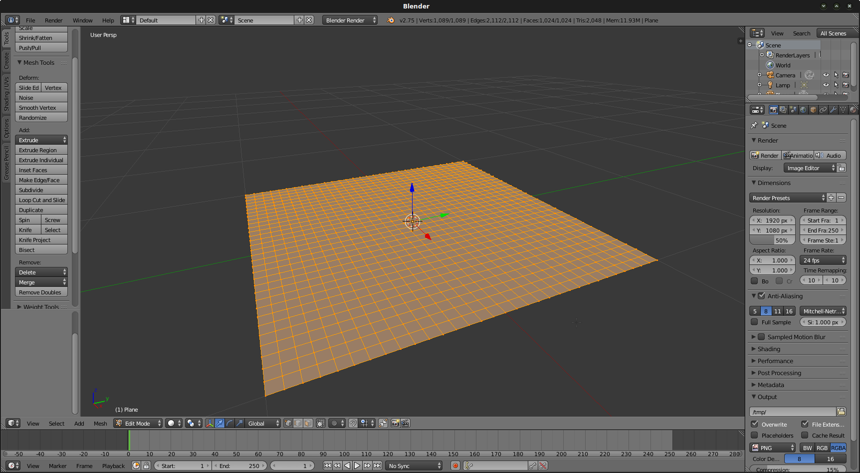
Your mesh is now subdivided, which means we added vertices to the plane mesh that we will later be able to move. Job’s not finished yet: in order to texture this mesh a proper UV map is necessary. Currently, the default UV map contains only the 4 corner vertices we had at the beginning. However, we now have more, and we want to be able to texture over the whole mesh correctly.
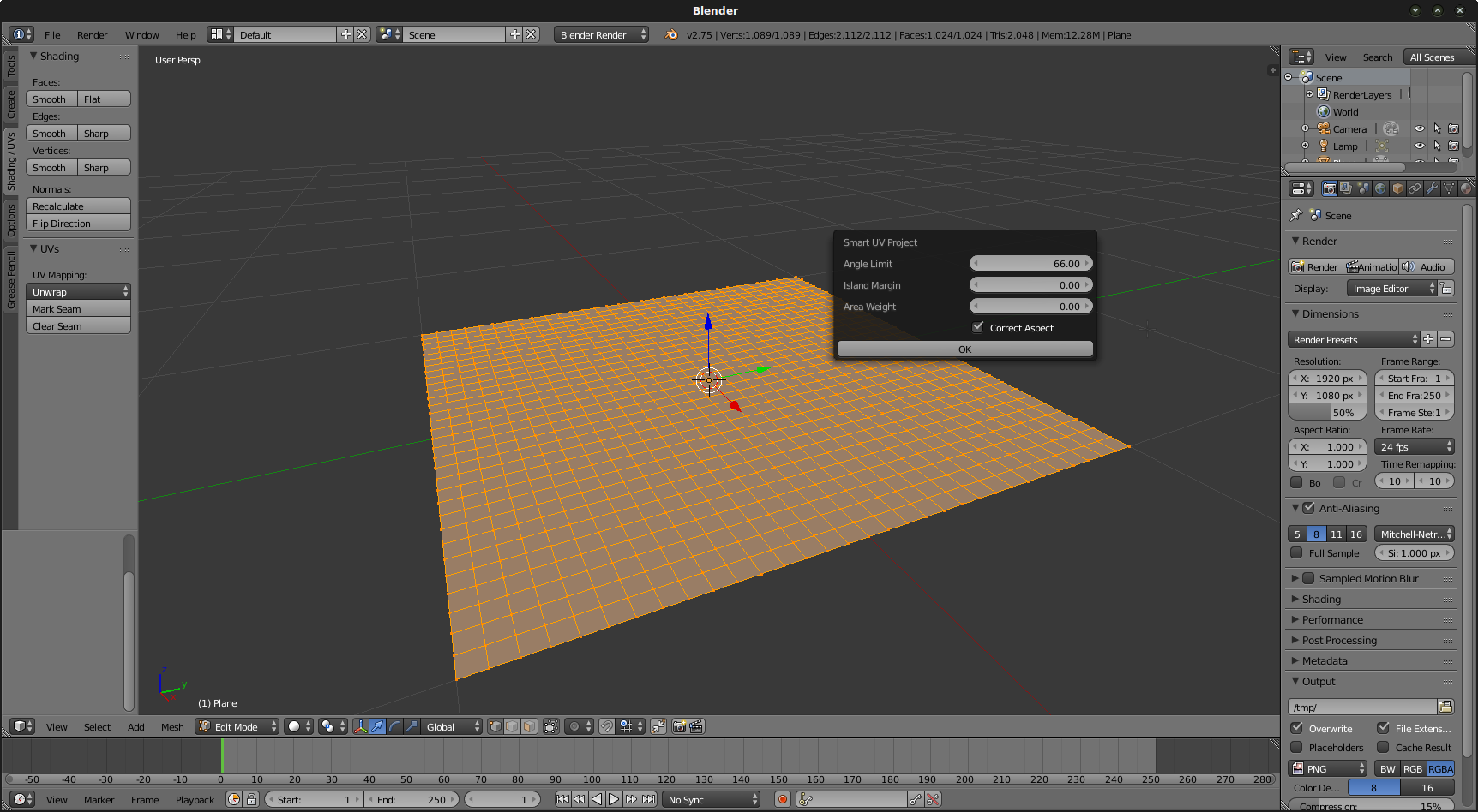
If all the vertices of your mesh are not selected, select them all (hit “A”). They must appear orange, not black. Then, in the Shading/UVs button group to the left, click the “Unwrap” button (or simply hit “U”) and select “Smart UV Project”. Keep the default options and hit “Ok”.
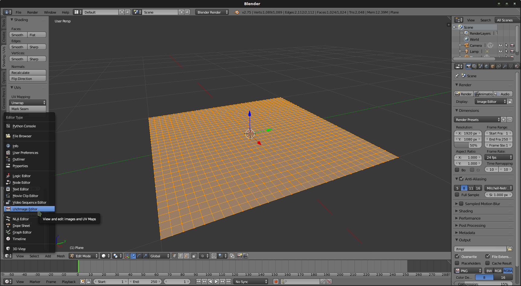
Now, we need to switch our view to “UV/Image editor”.
Select all the vertices again (“A”) then in the UV menu, select “Export UV Layout”.
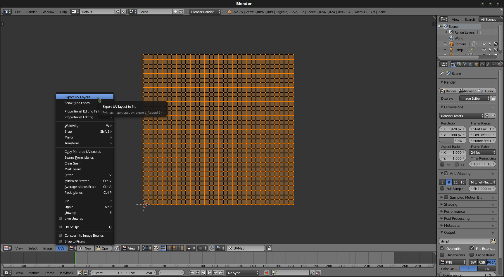
Export the layout as a PNG file. Name it “plane.png” and save it in your Godot project folder. Now, let’s export our mesh as an OBJ file. Top of the screen, click “File/Export/Wavefront (obj)”. Save your object as “plane.obj” in your Godot project folder.
Shader magic
Let’s now open Godot Editor.
Create a new project in the folder you previously created and name it what you want.
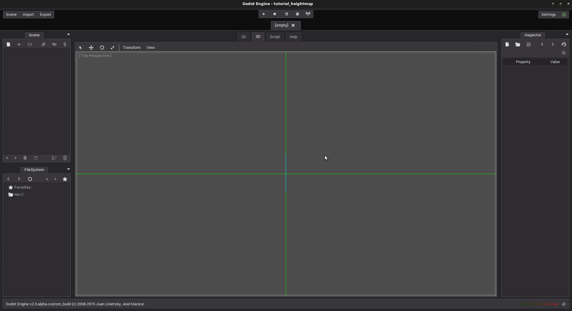
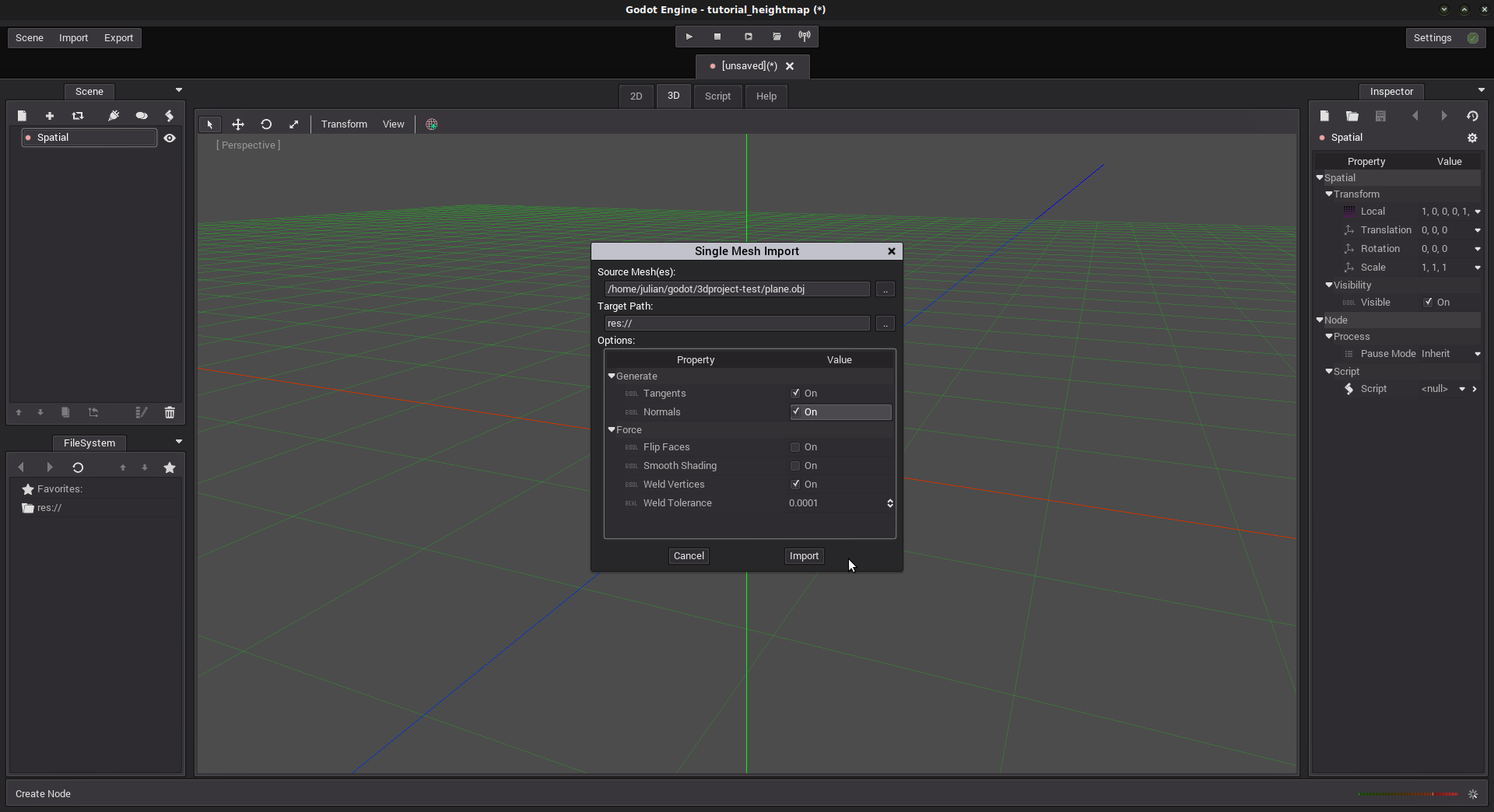
In our default scene (3D), create a root node “Spatial”. Next, import the mesh OBJ file. Click “Import”, choose “3D Mesh” and select your plane.obj file, set the target path as “/” (or wherever you want in your project folder).
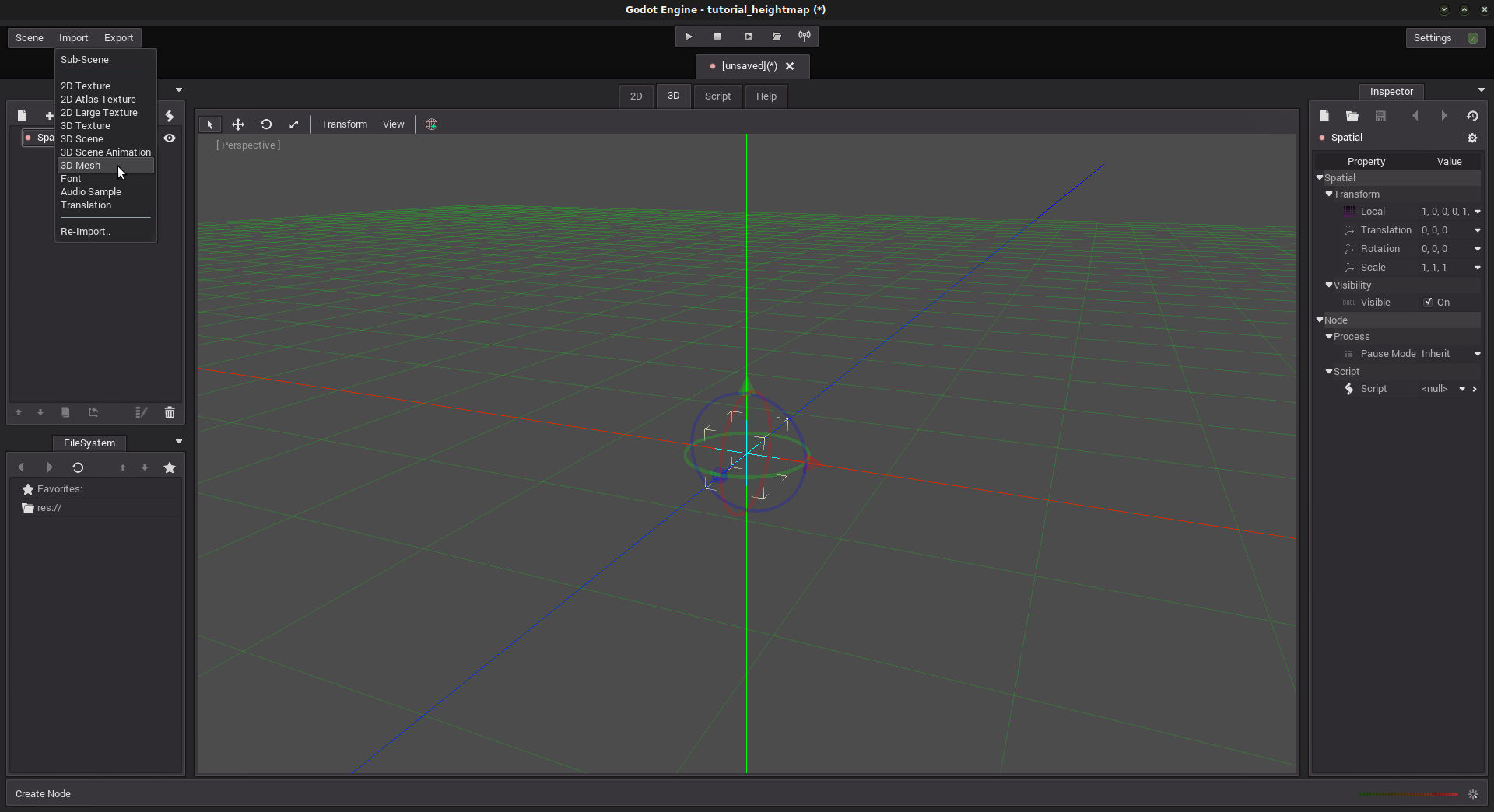
I like to check “Normals” in the import pop-up so the import will also consider faces normals, which can be useful (even if we don’t use them in this tutorial). Your mesh is now displayed in the FileSystem in “res://”.
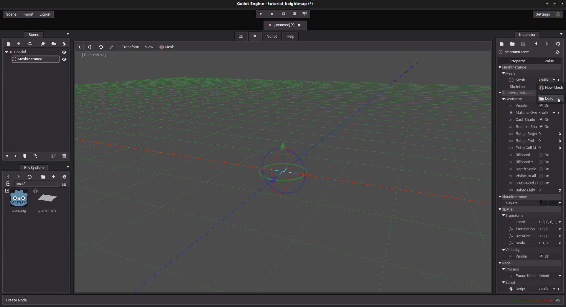
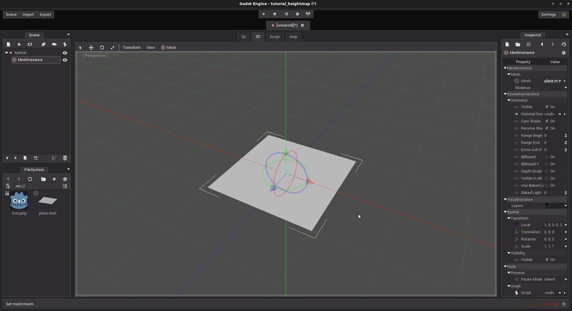
Create a MeshInstance node. In the Inspector, load the mesh we just imported. Select “plane.msh” and hit ok.
Great! Our plane is now rendered in the 3D view.
It is time to add some shader stuff. In the Inspector, in the “Material Override” line, add a “New ShaderMaterial”. Edit it by clicking the “>” button just right to it.
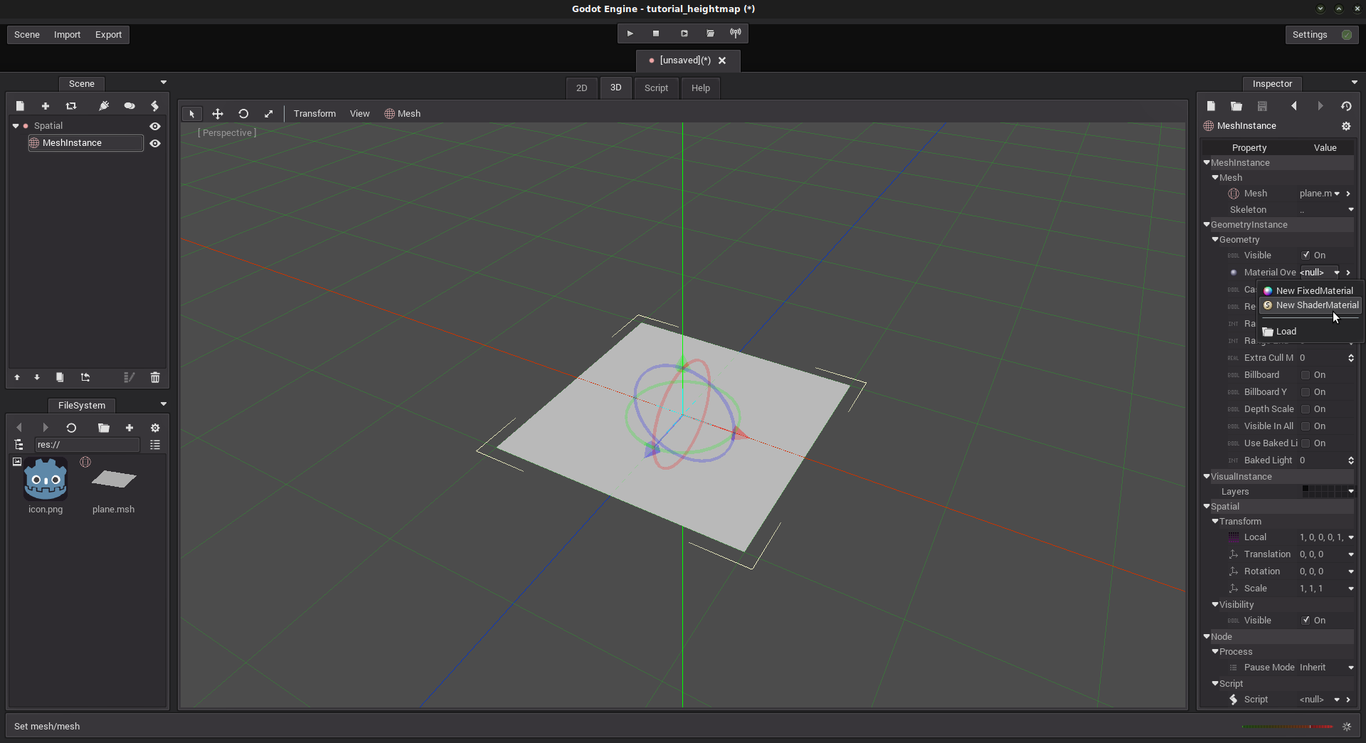
You have two ways to create a shader: by code (MaterialShader), or using a shader graph (MaterialShaderGraph). The second one is a bit more visual, but we will not cover it for now. Create a “New MaterialShader”.
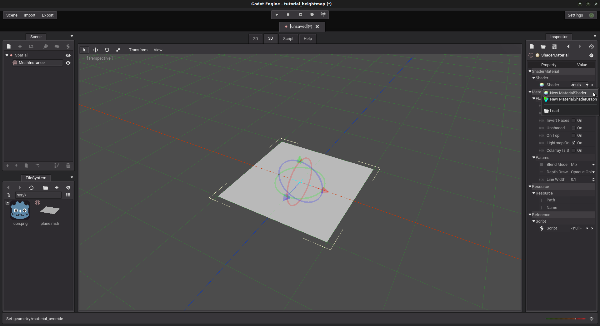
Edit it by clicking the “>” button just right to it. The Shaders editor opens.
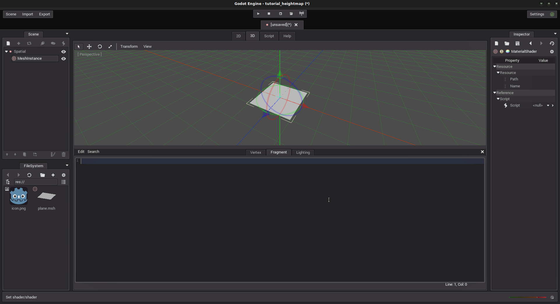
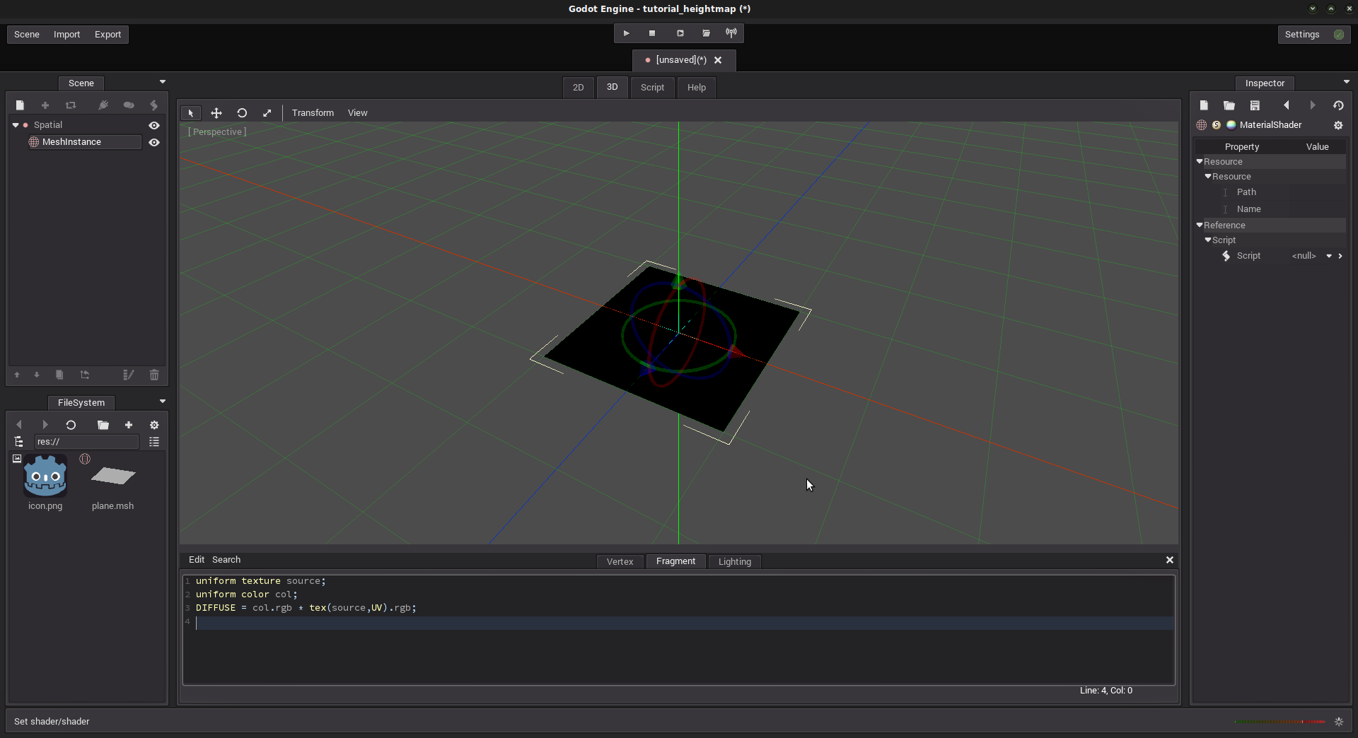
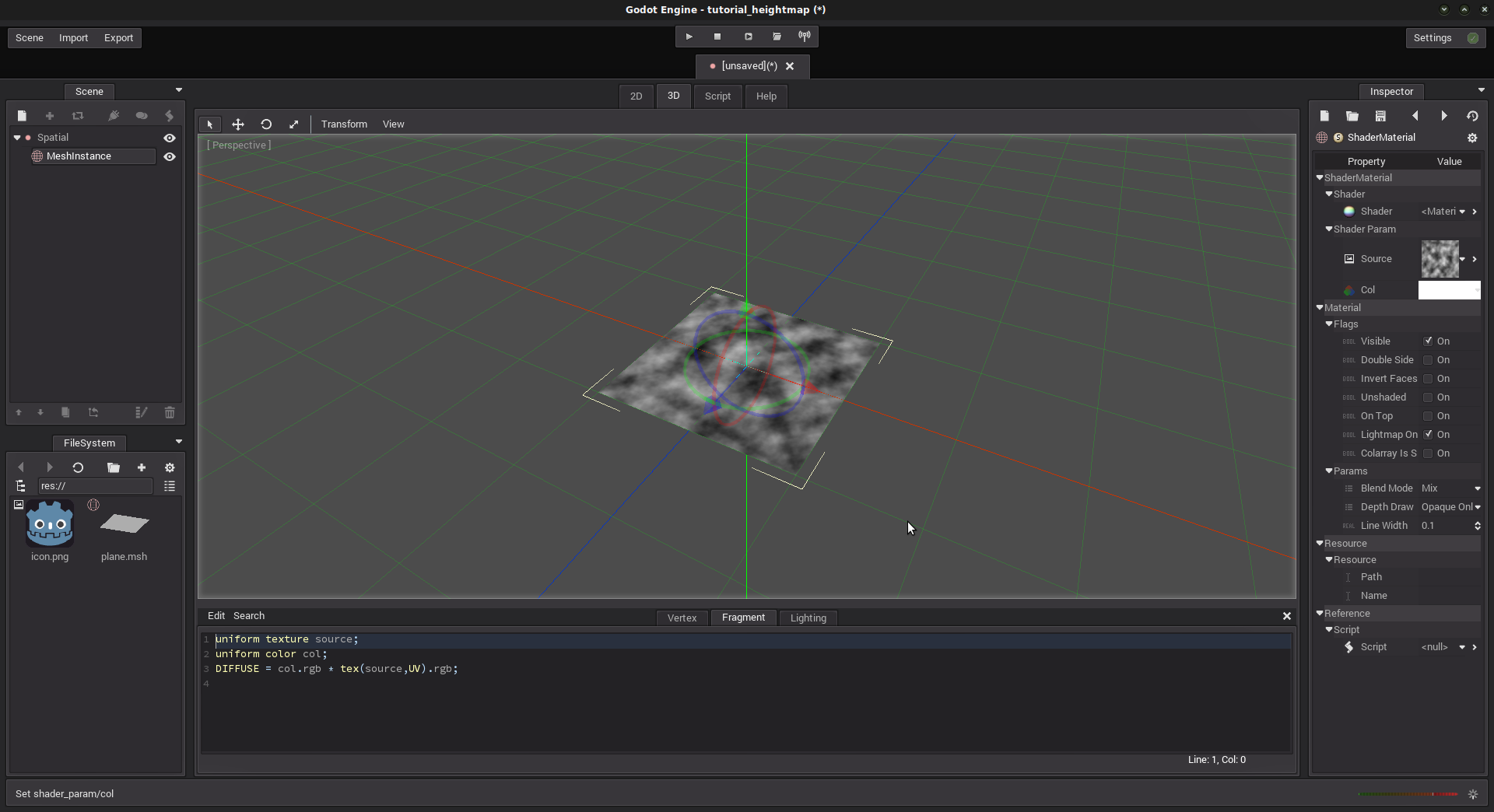
The Vertex tab is for the Vertex shader, and the Fragment tab is for the Fragment shader. No need to explain what both of them do, right? If so, head to the Shading language page. Else, let’s start with the Fragment shader. This one is used to texture the plane using an image. For this example, we will texture it with the heightmap image itself, so we’ll actually see mountains as brighter regions and canyons as darker regions. Use this code:
uniform texture source;
uniform color col;
DIFFUSE = col.rgb * tex(source,UV).rgb;
This shader is very simple (it actually comes from the Shading language page). What it basically does is take 2 parameters that we have to provide from outside the shader (“uniform”):
- the texture file
- a color
Then, we multiply every pixel of the image given by
tex(source, UV).rgbby the color definedcoland we set it to DIFFUSE variable, which is the rendered color. Remember that theUVvariable is a shader variable that returns the 2D position of the pixel in the texture image, according to the vertex we are currently dealing with. That is the use of the UV Layout we made before. The colorcolis actually not necessary to display the texture, but it is interesting to play and see how it does, right?
However, the plane is displayed black! This is because we didn’t set the texture file and the color to use.
In the Inspector, click the “Previous” button to get back to the
ShaderMaterial. This is where you want to set the texture and the
color. In “Source”, click “Load” and select the texture file
“heightmap.png”. But the mesh is still black! This is because our
Fragment shader multiplies each pixel value of the texture by the
col parameter. However, this color is currently set to black
(0,0,0), and as you know, 0*x = 0 ;) . Just change the col
parameter to another color to see your texture appear:
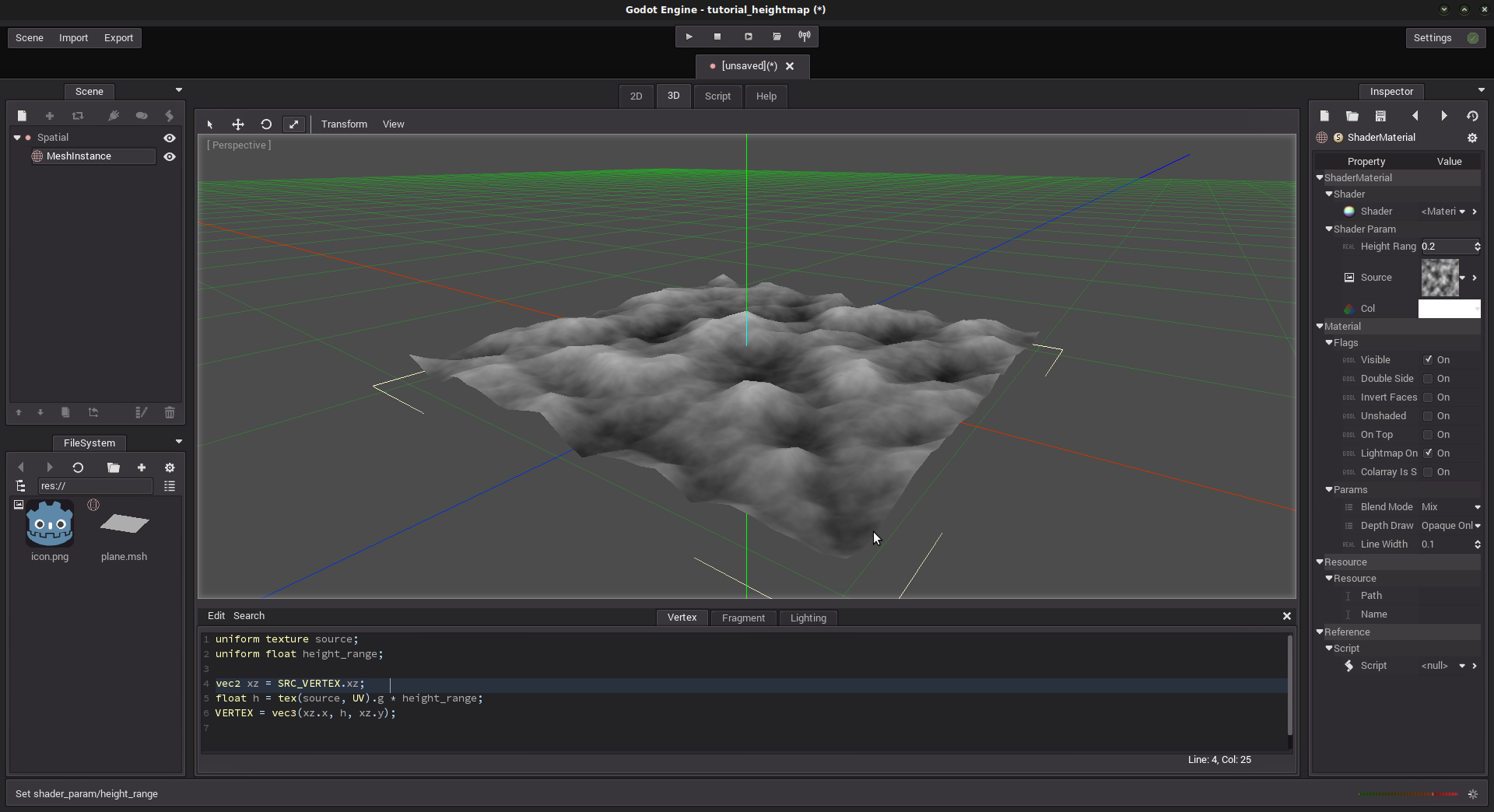
Good. Now, the Vertex Shader.
The Vertex Shader is the first shader to be executed by the pipeline. It deals with vertices.
Click the “Vertex” tab to switch, and paste this code:
uniform texture source;
uniform float height_range;
vec2 xz = SRC_VERTEX.xz;
float h = tex(source, UV).g * height_range;
VERTEX = vec3(xz.x, h, xz.y);
VERTEX = MODELVIEW_MATRIX *  VERTEX;
This shader uses two “uniform” parameters. The source parameter is
already set for the fragment shader. Thus, the same image will be used
in this shader as the heightmap. The height_range parameter is a
parameter that we will use to increase the height effect.
At line 3, we save the x and z position of the SRC_VERTEX, because we do not want them to change : the plane must remain square. Remember that Y axis corresponds to the “altitude”, which is the only one we want to change with the heightmap.
At line 4, we compute an h variable by multiplying the pixel value
at the UV position and the height_range. As the heightmap is a
greyscale image, all r, g and b channels contain the same value. I
used g, but any of r, g and b have the same effect.
At line 5, we set the current vertex’ position at (xz.x, h, xz.y) position. Concerning xz.y remember that its type is “vec2”. Thus, its components are x and y. The y component simply contains the z position we set at line 3.
Finally, at line 6, we multiply the vertex by the model/view matrix in order to set its position according to camera position. If you try to comment this line, you’ll see that the mesh behaves weird as you move and rotate the camera.
That’s all good, but our plane remains flat. This is because the
height_range value is 0. Increase this value to observe the mesh
distort and take to form of the terrain we set before: