Custom drawing in 2D
Why?
Godot has nodes to draw sprites, polygons, particles, and all sorts of stuff. For most cases this is enough, but not always. Before crying in fear, angst, and rage because a node to draw that-specific-something does not exist… it would be good to know that it is possible to easily make any 2D node (be it Control or Node2D based) draw custom commands. It is really easy to do it too.
But…
Custom drawing manually in a node is really useful. Here are some examples why:
- Drawing shapes or logic that is not handled by nodes (example: making a node that draws a circle, an image with trails, a special kind of animated polygon, etc).
- Visualizations that are not that compatible with nodes: (example: a tetris board). The tetris example uses a custom draw function to draw the blocks.
- Managing drawing logic of a large amount of simple objects (in the hundreds of thousands). Using a thousand nodes is probably not nearly as efficient as drawing, but a thousand of draw calls are cheap. Check the “Shower of Bullets” demo as example.
- Making a custom UI control. There are plenty of controls available, but it’s easy to run into the need to make a new, custom one.
OK, how?
Add a script to any CanvasItem derived node, like Control or Node2D. Override the _draw() function.
extends Node2D

func _draw():
    #your draw commands here
    pass
Draw commands are described in the CanvasItem class reference. There are plenty of them.
Updating
The _draw() function is only called once, and then the draw commands are cached and remembered, so further calls are unnecessary.
If re-drawing is required because a state or something else changed, simply call CanvasItem.update() in that same node and a new _draw() call will happen.
Here is a little more complex example. A texture variable that will be redrawn if modified:
extends Node2D

export var texture setget _set_texture

func _set_texture(value):
    #if the texture variable is modified externally,
    #this callback is called.
    texture=value #texture was changed
    update() #update the node

func _draw():
    draw_texture(texture,Vector2())
In some cases, it may be desired to draw every frame. For this, just call update() from the _process() callback, like this:
extends Node2D

func _draw():
    #your draw commands here
    pass

func _process(delta):
    update()

func _ready():
    set_process(true)
An example: drawing circular arcs
We will now use the custom drawing functionality of the Godot Engine to draw something that Godot doesn’t provide functions for. As an example, Godot provides a draw_circle() function that draws a whole circle. However, what about drawing a portion of a circle? You will have to code a function to perform this, and draw it yourself.
Arc function
An arc is defined by its support circle parameters, that is: the center position, and the radius. And the arc itself is then defined by the angle it starts from, and the angle it stops at. These are the 4 parameters we have to provide to our drawing. We’ll also provide the color value so we can draw the arc in different colors if we wish.
Basically, drawing a shape on screen requires it to be decomposed into a certain number of points linked one to the following one. As you can imagine, the more points your shape is made of, the smoother it will appear, but the heavier it will be in terms of processing cost. In general, if your shape is huge (or in 3D, close to the camera), it will require more points to be drawn without showing angular-looking. On the contrary, if you shape is small (or in 3D, far from the camera), you may reduce its number of points to save processing costs. This is called Level of Detail (LoD). In our example, we will simply use a fixed number of points, no matter the radius.
func draw_circle_arc( center, radius, angle_from, angle_to, color ):
    var nb_points = 32
    var points_arc = Vector2Array()

    for i in range(nb_points+1):
        var angle_point = angle_from + i*(angle_to-angle_from)/nb_points - 90
        var point = center + Vector2( cos(deg2rad(angle_point)), sin(deg2rad(angle_point)) ) * radius
        points_arc.push_back( point )

    for indexPoint in range(nb_points):
        draw_line(points_arc[indexPoint], points_arc[indexPoint+1], color)
Remember the number of points our shape has to be decomposed into? We fixed this number in the nb_points variable to a value of 32. Then, we initialize an empty Vector2Array, which is simply an array of Vector2.
Next step consists in computing the actual positions of these 32 points that compose arc. This is done in the first for-loop: we iterate over the number of points we want to compute the positions, plus one to include the last point. We first determine the angle of each point, between the starting and ending angles.
The reason why each angle is reduced of 90° is that we will compute 2D positions out of each angle using trigonometry (you know, cosine and sine stuff…). However, to be simple, cos() and sin() use radians, not degrees. The angle of 0° (0 radian) starts at 3 o’clock, although we want to start counting at 0 o’clock. So, we just reduce each angle of 90° in order to start counting from 0’clock.
The actual position of a point located on a circle at angle ‘angle’ (in radians) is given by Vector2(cos(angle), sin(angle)). Since cos() and sin() return values between -1 and 1, the position is located on a circle of radius 1. To have this position on our support circle, which has a radius of ‘radius’, we simply need to multiply the position by ‘radius’. Finally, we need to position our support circle at the ‘center’ position, which is performed by adding it to our Vector2 value. Finally, we insert the point in the Vector2Array which was previously defined.
Now, we need to actually draw our points. As you can imagine, we will not simply draw our 32 points: we need to draw everything that is between each of them. We could have computed every point ourselves using the previous method, and draw it one by one, but this it too complicated and inefficient (except if explicitly needed). So, we simply draw lines between each pair of points. Unless the radius of our support circle is very big, the length of each line between a pair of points will never be long enough to see them. If this happens, we simply would need to increase the number of points.
Draw the arc on screen
We now have a function that draws stuff on screen: it is time to call it in the _draw() function.
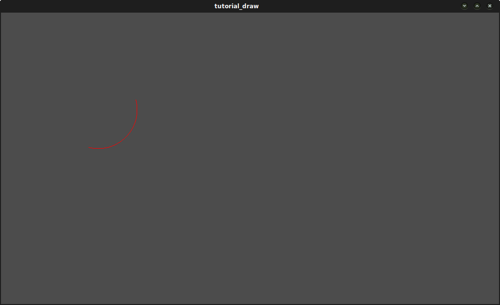
func _draw():
    var center = Vector2(200,200)
    var radius = 80
    var angle_from = 75
    var angle_to = 195
    var color = Color(1.0, 0.0, 0.0)
    draw_circle_arc( center, radius, angle_from, angle_to, color )
Result:
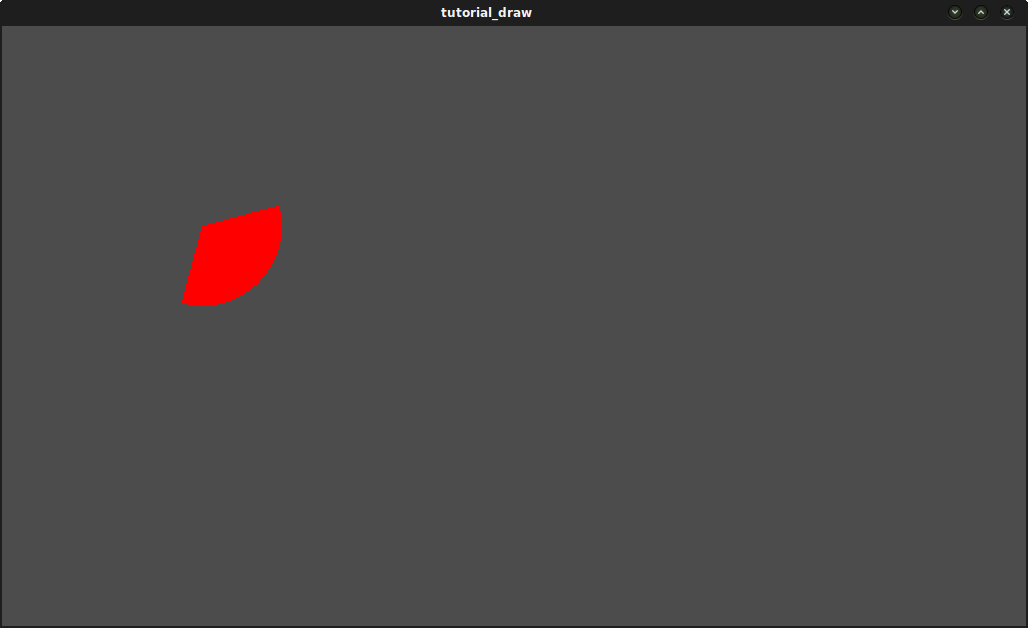
Arc polygon function
We can take this a step further and write a function that draws the plain portion of the disc defined by the arc, not only its shape. The method is exactly the same a previously, except that we draw a polygon instead of lines:
func draw_circle_arc_poly( center, radius, angle_from, angle_to, color ):
    var nb_points = 32
    var points_arc = Vector2Array()
    points_arc.push_back(center)
    var colors = ColorArray([color])

    for i in range(nb_points+1):
        var angle_point = angle_from + i*(angle_to-angle_from)/nb_points - 90
        points_arc.push_back(center + Vector2( cos( deg2rad(angle_point) ), sin( deg2rad(angle_point) ) ) * radius)
    draw_polygon(points_arc, colors)
Dynamic custom drawing
Alright, we are now able to draw custom stuff on screen. However, it is very static: let’s make this shape turn around the center. The solution to do this is simply to change the angle_from and angle_to values over time. For our example, we will simply increment them by 50. This increment value has to remain constant, else the rotation speed will change accordingly.
First, we have to make both angle_from and angle_to variables global at the top of our script. Also note that you can store them in other nodes and access them using get_node().
extends Node2D

var rotation_ang = 50
var angle_from = 75
var angle_to = 195
We make these values change in the _process(delta) function. To activate this function, we need to call set_process(true) in the _ready() function.
We also increment our angle_from and angle_to values here. However, we must not forget to wrap() the resulting values between 0 and 360°! That is, if the angle is 361°, then it is actually 1°. If you don’t wrap these values, the script will work correctly but angles values will grow bigger and bigger over time, until they reach the maximum integer value Godot can manage (2^31 - 1). When this happens, Godot may crash or produce unexpected behavior. Since Godot doesn’t provide a wrap() function, we’ll create it here, as it is relatively simple.
Finally, we must not forget to call the update() function, which automatically calls _draw(). This way, you can control when you want to refresh the frame.
func _ready():
    set_process(true)

func wrap(value, min_val, max_val):
    var f1 = value - min_val
    var f2 = max_val - min_val
    return fmod(f1, f2) + min_val

func _process(delta):
    angle_from += rotation_ang
    angle_to += rotation_ang

    # we only wrap angles if both of them are bigger than 360
    if (angle_from > 360 && angle_to > 360):
        angle_from = wrap(angle_from, 0, 360)
        angle_to = wrap(angle_to, 0, 360)
    update()
Also, don’t forget to modify the _draw() function to make use of these variables:
func _draw():
       var center = Vector2(200,200)
       var radius = 80
       var color = Color(1.0, 0.0, 0.0)

       draw_circle_arc( center, radius, angle_from, angle_to, color )
Let’s run! It works, but the arc is rotating insanely fast! What’s wrong?
The reason is that your GPU is actually displaying the frames as fast as he can. We need to “normalize” the drawing by this speed. To achieve, we have to make use of the ‘delta’ parameter of the _process() function. ‘delta’ contains the time elapsed between the two last rendered frames. It is generally small (about 0.0003 seconds, but this depends on your hardware). So, using ‘delta’ to control your drawing ensures your program to run at the same speed on every hardware.
In our case, we simply need to multiply our ‘rotation_ang’ variable by ‘delta’ in the _process() function. This way, our 2 angles will be increased by a much smaller value, which directly depends on the rendering speed.
func _process(delta):
    angle_from += rotation_ang * delta
    angle_to += rotation_ang * delta

    # we only wrap angles if both of them are bigger than 360
    if (angle_from > 360 && angle_to > 360):
        angle_from = wrap(angle_from, 0, 360)
        angle_to = wrap(angle_to, 0, 360)
    update()
Let’s run again! This time, the rotation displays fine!