Lights and shadows
Introduction
Light sources emit light that mixes with the materials and produces a visible result. Light can come from several types of sources in a scene:
- From the Material itself in the form of the emission color (though it does not affect nearby objects unless baked).
- Light Nodes: Directional, Omni and Spot.
- Ambient Light in the Environment.
- Baked Light (read Baked lightmaps).
The emission color is a material property. You can read more about it in the Spatial Material tutorial.
Light nodes
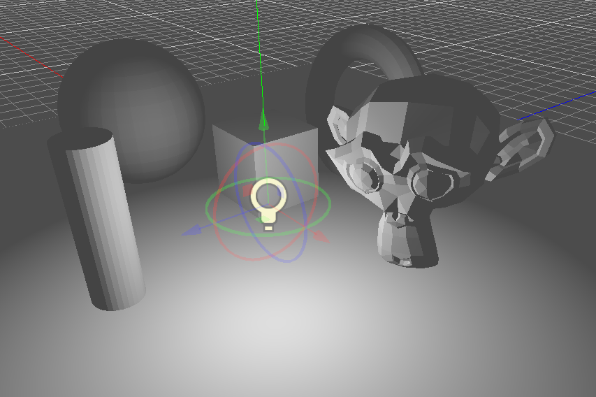
There are three types of light nodes: Directional light, Omni light and Spot light. Let’s take a look at the common parameters for lights:
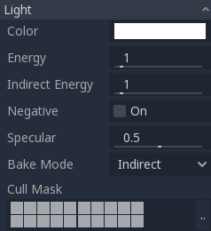
Each one has a specific function:
- Color: Base color for emitted light.
- Energy: Energy multiplier. This is useful for saturating lights or working with High dynamic range.
- Indirect Energy: Secondary multiplier used with indirect light (light bounces). This works in baked light or GIProbe.
- Negative: Light becomes subtractive instead of additive. It’s sometimes useful to manually compensate some dark corners.
- Specular: Affects the intensity of the specular blob in objects affected by this light. At zero, this light becomes a pure diffuse light.
- Bake Mode: Sets the bake mode for the light. For more information see Baked lightmaps
- Cull Mask: Objects that are in the selected layers below will be affected by this light.
Shadow mapping
Lights can optionally cast shadows. This gives them greater realism (light does not reach occluded areas), but it can incur a bigger performance cost. There is a list of generic shadow parameters, each also has a specific function:
- Enabled: Check to enable shadow mapping in this light.
- Color: Areas occluded are multiplied by this color. It is black by default, but it can be changed to tint shadows.
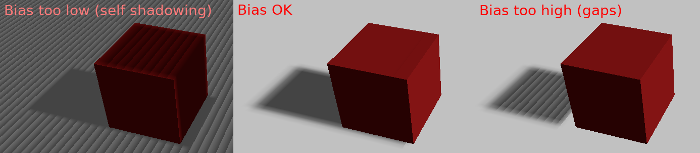
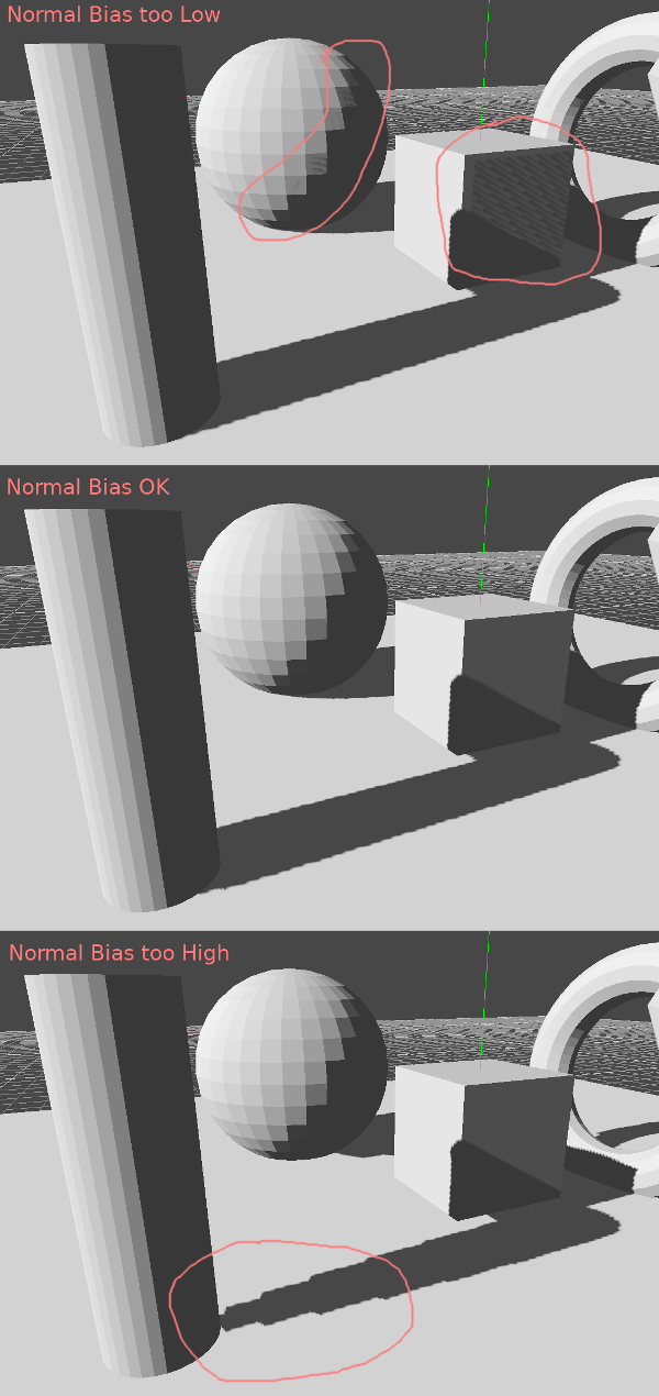
- Bias: When this parameter is too small, self shadowing occurs. When too large, shadows separate from the casters. Tweak to what works best for you.
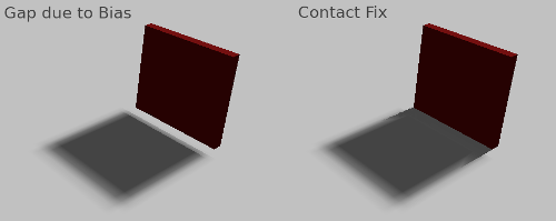
- Contact: Performs a short screen-space raycast to reduce the gap generated by the bias. Contact shadows are only available when using the GLES3 backend.
- Reverse Cull Faces: Some scenes work better when shadow mapping is rendered with face-culling inverted.
Below is an image of what tweaking bias looks like. Default values work for most cases, but in general it depends on the size and complexity of geometry.
Finally, if gaps can’t be solved, the Contact option can help:
Any sort of bias issues can always be fixed by increasing the shadow map resolution, although that may lead to decreased performance on low-end hardware.
Directional light
This is the most common type of light and represents a light source very far away (such as the sun). It is also the cheapest light to compute and should be used whenever possible (although it’s not the cheapest shadow-map to compute, but more on that later).
Directional light models an infinite number of parallel light rays covering the whole scene. The directional light node is represented by a big arrow which indicates the direction of the light rays. However, the position of the node does not affect the lighting at all and can be anywhere.
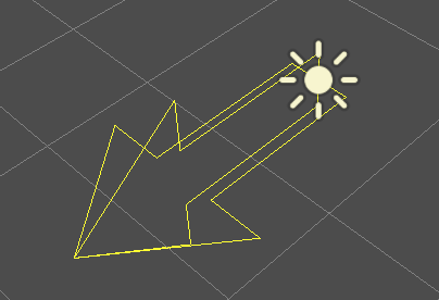
Every face whose front-side is hit by the light rays is lit, while the others stay dark. Most light types have specific parameters, but directional lights are pretty simple in nature, so they don’t.
Directional shadow mapping
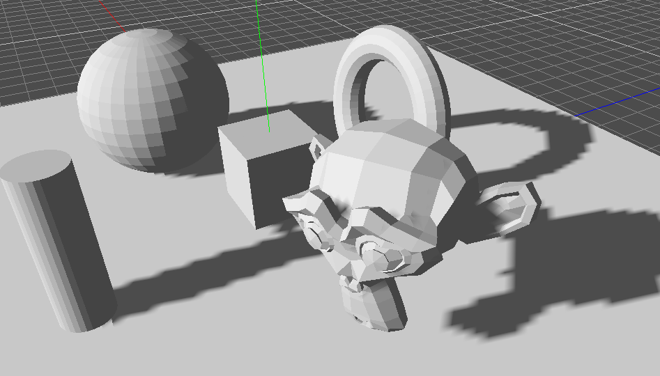
To compute shadow maps, the scene is rendered (only depth) from an orthogonal point of view that covers the whole scene (or up to the max distance). There is, however, a problem with this approach because objects closer to the camera receive blocky shadows.
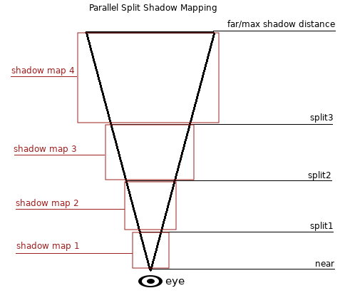
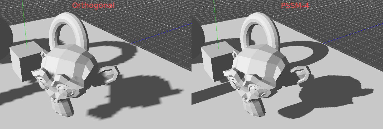
To fix this, a technique named “Parallel Split Shadow Maps” (or PSSM) is used. This splits the view frustum in 2 or 4 areas. Each area gets its own shadow map. This allows small areas close to the viewer to have the same shadow resolution as a huge, far-away area.
With this, shadows become more detailed:
To control PSSM, a number of parameters are exposed:
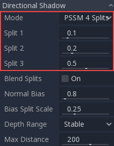
Each split distance is controlled relative to the camera far (or shadow Max Distance if greater than zero), so 0.0 is the eye position and 1.0 is where the shadow ends at a distance. Splits are in-between. Default values generally work well, but tweaking the first split a bit is common to give more detail to close objects (like a character in a third person game).
Always make sure to set a shadow Max Distance according to what the scene needs. A lower maximum distance will result in better-looking shadows.
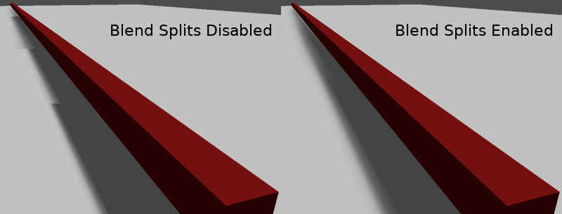
Sometimes, the transition between a split and the next can look bad. To fix this, the “Blend Splits” option can be turned on, which sacrifices detail in exchange for smoother transitions:
The “Normal Bias” parameter can be used to fix special cases of self shadowing when objects are perpendicular to the light. The only downside is that it makes the shadow a bit thinner.
The “Bias Split Scale” parameter can control extra bias for the splits that are far away. If self shadowing occurs only on the splits far away, this value can fix them.
Finally, the “Depth Range” has two settings:
- Stable: Keeps the shadow stable while the camera moves, and the blocks that appear in the outline when close to the shadow edges remain in-place. This is the default and generally desired, but it reduces the effective shadow resolution.
- Optimized: Tries to achieve the maximum resolution available at any given time. This may result in a “moving saw” effect on shadow edges, but at the same time the shadow looks more detailed (so this effect may be subtle enough to be forgiven).
Just experiment which setting works better for your scene.
Shadowmap size for directional lights can be changed in Project Settings -> Rendering -> Quality:
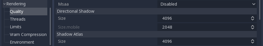
Increasing it can solve bias problems, but decrease performance. Shadow mapping is an art of tweaking.
Omni light
Omni light is a point source that emits light spherically in all directions up to a given radius.
In real life, light attenuation is an inverse function, which means omni lights don’t have a radius. This is a problem because it means computing several omni lights would become demanding.
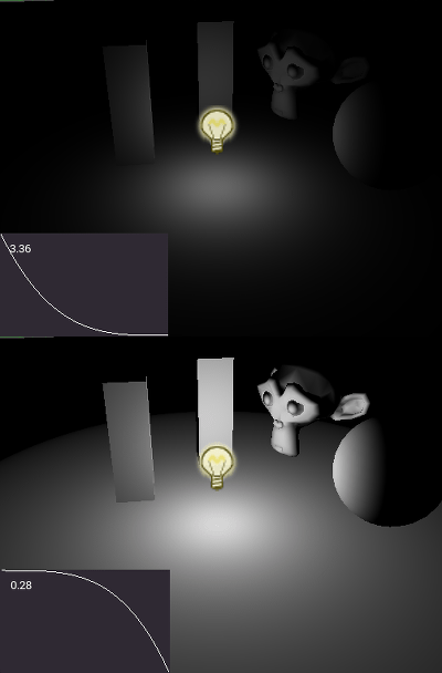
To solve this, a Range is introduced together with an attenuation function.
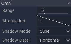
These two parameters allow tweaking how this works visually in order to find aesthetically pleasing results.
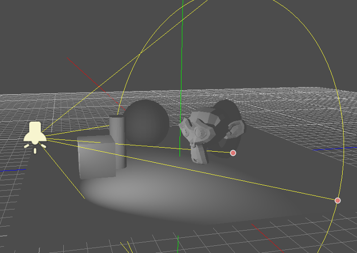
Omni shadow mapping
Omni light shadow mapping is relatively straightforward. The main issue that needs to be considered is the algorithm used to render it.
Omni Shadows can be rendered as either “Dual Paraboloid” or “Cube Mapped”. The former renders quickly, but can cause deformations, while the later is more correct, but costlier.
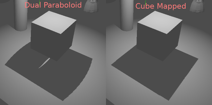
If the objects being rendered are mostly irregular, Dual Paraboloid is usually enough. In any case, as these shadows are cached in a shadow atlas (more on that at the end), it may not make a difference in performance for most scenes.
Spot light
Spot lights are similar to omni lights, except they emit light only into a cone (or “cutoff”). They are useful to simulate flashlights, car lights, reflectors, spots, etc. This type of light is also attenuated towards the opposite direction it points to.
Spot lights share the same Range and Attenuation as OmniLight, and add two extra parameters:
- Angle: The aperture angle of the light
- Angle Attenuation: The cone attenuation, which helps soften the cone borders.
Spot shadow mapping
Spots don’t need any parameters for shadow mapping. Keep in mind that, at more than 89 degrees of aperture, shadows stop functioning for spots, and you should consider using an Omni light instead.
Shadow atlas
Unlike Directional lights, which have their own shadow texture, Omni and Spot lights are assigned to slots of a shadow atlas. This atlas can be configured in Project Settings -> Rendering -> Quality -> Shadow Atlas.
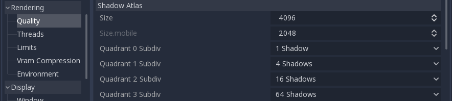
The resolution applies to the whole Shadow Atlas. This atlas is divided into four quadrants:
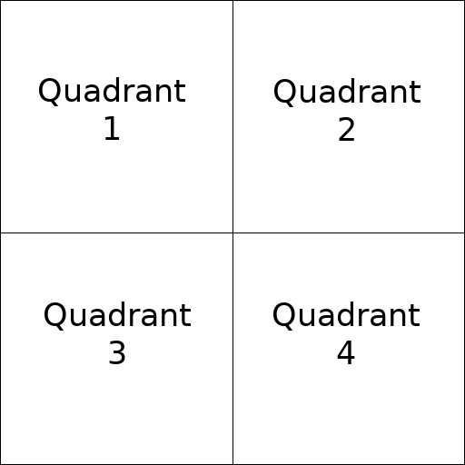
Each quadrant can be subdivided to allocate any number of shadow maps; the following is the default subdivision:
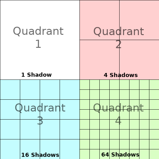
The allocation logic is simple. The biggest shadow map size (when no subdivision is used) represents a light the size of the screen (or bigger). Subdivisions (smaller maps) represent shadows for lights that are further away from view and proportionally smaller.
Every frame, the following procedure is performed for all lights:
- Check if the light is on a slot of the right size. If not, re-render it and move it to a larger/smaller slot.
- Check if any object affecting the shadow map has changed. If it did, re-render the light.
- If neither of the above has happened, nothing is done, and the shadow is left untouched.
If the slots in a quadrant are full, lights are pushed back to smaller slots, depending on size and distance.
This allocation strategy works for most games, but you may want to use a separate one in some cases (for example, a top-down game where all lights are around the same size and quadrants may all have the same subdivision).
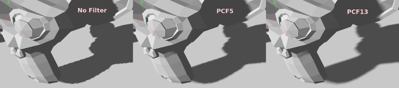
Shadow filter quality
The filter quality of shadows can be tweaked. This can be found in Project Settings -> Rendering -> Quality -> Shadows. Godot supports no filter, PCF5 and PCF13.
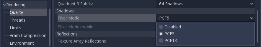
It affects the blockyness of the shadow outline: