Vertex displacement with shaders
Introduction
This tutorial will teach you how to displace the vertices of a Plane Mesh inside a shader. Vertex displacement can be used for a wide variety of effects, but most commonly it is used as a quick way to turn a flat plane into a simple terrain. Typically this is done using a heightmap, but in order to keep everything self contained, in this tutorial we will use noise in a shader. At the end of this tutorial we will have a deformed plane that looks like a miniature terrain complete with dynamic lighting.
By reading this tutorial you should gain a basic understanding of:
- How to create and subdivide a Plane Mesh
- How to create and assign a material to a Mesh
- How to write a Shader that displaces the vertices of a Mesh
- How to pass values (Uniforms) into a Shader to update the Mesh in realtime
- How to approximate normals from a height function
- How to use a light with a custom material
The plane mesh
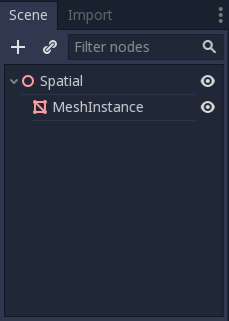
First, add a Spatial node to the scene to act as the root. Next, add a MeshInstance as a child.
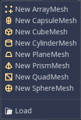
Select the newly created MeshInstance. Then click on the button that says “null” next to the Mesh in the Inspector. This will bring up a list of PrimitiveMeshes. Select “New PlaneMesh”.
The button will change into a small image of a plane. Click on it to enter into the Inspector for the Plane Mesh.
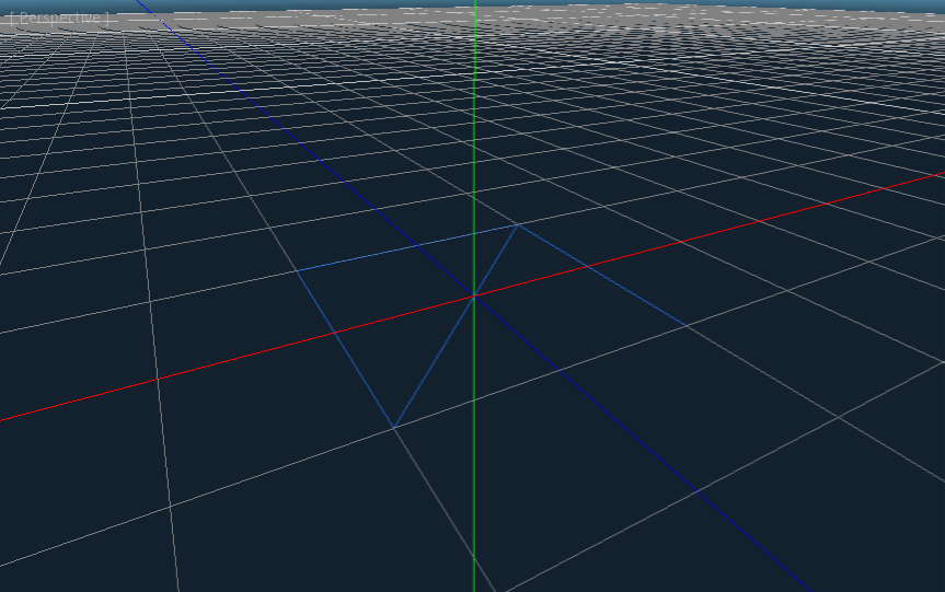
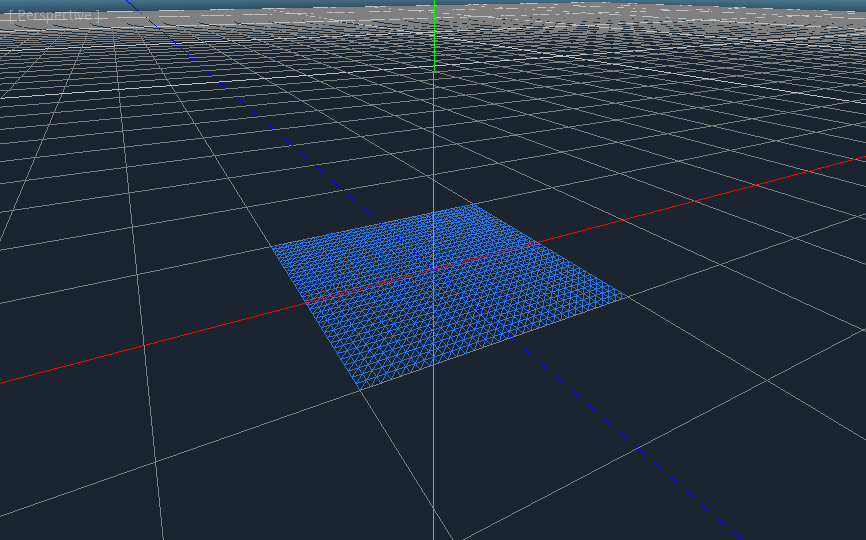
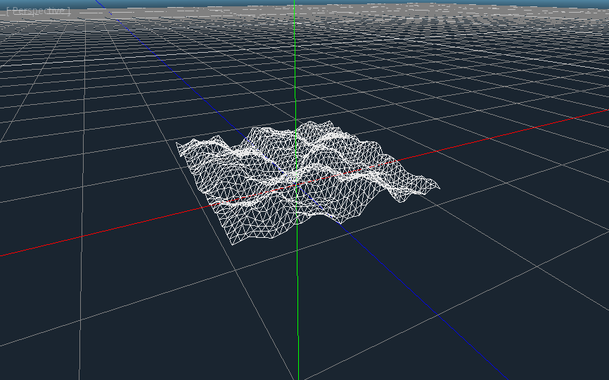
Then, in the viewport, click in the upper left corner where it says [Perspective]. A menu will appear. In the middle of the menu are options for how to display the scene. Select ‘Display Wireframe’.
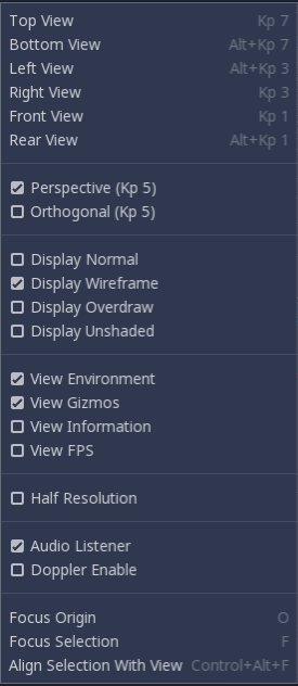
This will allow you to see the triangles making up the plane.
Now set the Subdivide Width and Subdivide Height to 32.
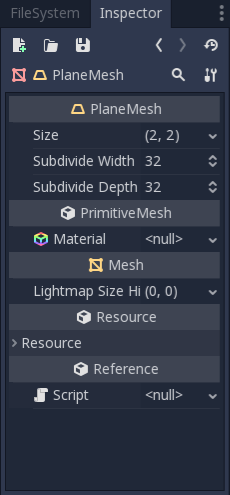
You can see that there are now way more triangles in the Mesh. This will give us more vertices to work with and thus allow us to add more detail.
Shader magic
Now that we have a Plane Mesh to draw lets setup the material that will deform the Mesh.
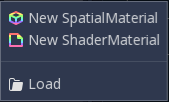
Click beside material in the Plane Mesh Menu and create a new ShaderMaterial.
Then click on the created ShaderMaterial.
Then click beside ‘shader’ and create a new Shader.
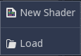
Click into the newly created Shader. You should now see Godot’s Shader editor.
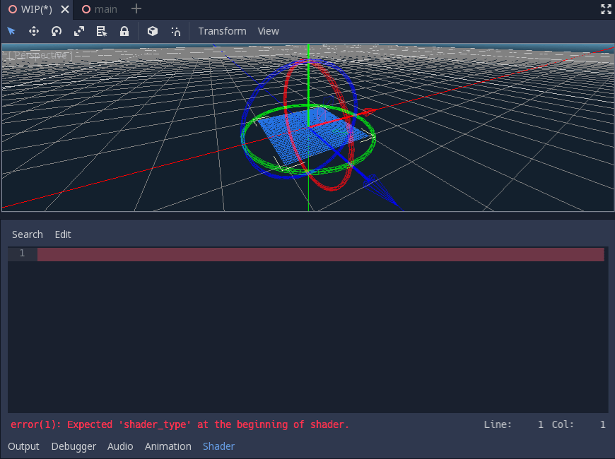
Notice how it is throwing an error? This is because the shader editor reloads shaders on
the fly automatically. The first thing Godot shaders need is a declaration of what type of
shader they are. Accordingly, we set the variable shader_type to spatial. One more
thing we will add is the render_mode, we will set it to unshaded. This means that
Godot won’t run the light shader on this object.
shader_type spatial;
render_mode unshaded;
This should remove the errors and your Mesh should turn white. If you were to comment out
the render_mode the plane would appear blue because it would pick up the sky colors.
Next we will define a vertex shader. The vertex shader determines where the vertices of your Mesh appear in the final scene. We will be using it to offset the height of each vertex and make our flat plane appear like a little terrain.
We define the vertex shader like so:
void vertex() {

}
With nothing in the vertex function Godot will use its default vertex shader. We can easily
start to make changes by adding a single line:
void vertex() {
  VERTEX.y += cos(VERTEX.x) * sin(VERTEX.z);
}
Adding this line you should get an image like the one below.
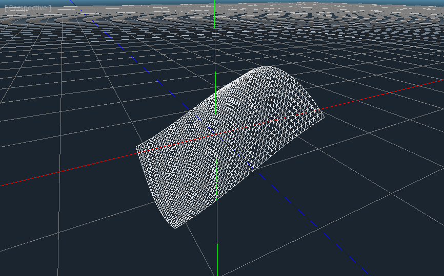
Okay, lets unpack this. The y value of the VERTEX is being increased. And we are passing
the x and z components of the VERTEX as arguments to cos and sin this gives us
a wave like appearance across the x and z axis.
What we want to achieve is the look of little hills, after all cos and sin already look kind of like
hills. We do so by scaling the inputs to the cos and sin functions.
void vertex() {
  VERTEX.y += cos(VERTEX.x * 4.0) * sin(VERTEX.z * 4.0);
}
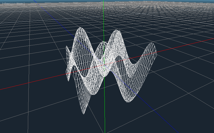
This looks better, but it is still too spiky. This is because cos and sin output values between -1 and 1,
so the range of the output is much too high. We correct this by multiplying the result by 0.5 to reduce the size.
void vertex() {
  VERTEX.y += cos(VERTEX.x * 4.0) * sin(VERTEX.z * 4.0) * 0.5;
}
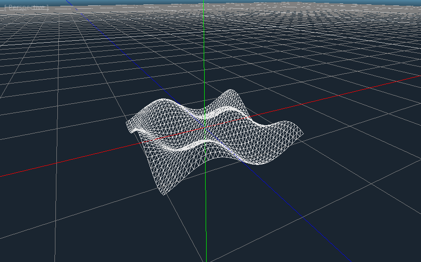
Looks much more hilly now. But cos and sin are boring. Lets move onto something more interesting.
Noise
Noise is a very popular tool for procedural generation. Think of it as similar to the cosine function where you have repeating hills except with noise each hill has a different height. Understanding noise is not necessary for this tutorial. There is nothing wrong with simply copying and pasting the code below.
The first function we use to generate the noise is the hash function. It gives the random height
for each of the hill tops.
float hash(vec2 p) {
  return fract(sin(dot(p * 17.17, vec2(14.91, 67.31))) * 4791.9511);
}
You will find similar functions to this all over the internet. It is lovingly referred to as the ‘one-liner hash function’. It works well for simple noise, but there are many better alternatives floating around as well. For this tutorial it will work fine.
Next we define the noise function. It smoothly interpolates between the random heights.
Again, if this code seems daunting, do not worry, just copy paste and move on with the tutorial.
float noise(vec2 x) {
  vec2 p = floor(x);
  vec2 f = fract(x);
  f = f * f * (3.0 - 2.0 * f);
  vec2 a = vec2(1.0, 0.0);
  return mix(mix(hash(p + a.yy), hash(p + a.xy), f.x),
         mix(hash(p + a.yx), hash(p + a.xx), f.x), f.y);
}
Lastly, to add detail we combine successive layers of noise using something called fractal brownian motion or FBM. Scary name aside FBM noise just adds together layers of noise with increase frequency and decreasing amplitude. To implement it we run over a for loop where we increase the frequency each level, decrease the amplitude, and calculate a new layer of noise.
float fbm(vec2 x) {
  float height = 0.0;
  float amplitude = 0.5;
  float frequency = 3.0;
  for (int i = 0; i < 6; i++){
    height += noise(x * frequency) * amplitude;
    amplitude *= 0.5;
    frequency *= 2.0;
  }
  return height;
}
We can now use this noise function in place of cos and sin in the previous section.
float height = fbm(VERTEX.xz * 4.0);
VERTEX.y += height * 0.5;
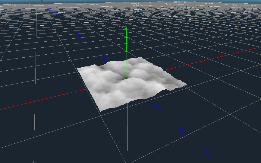
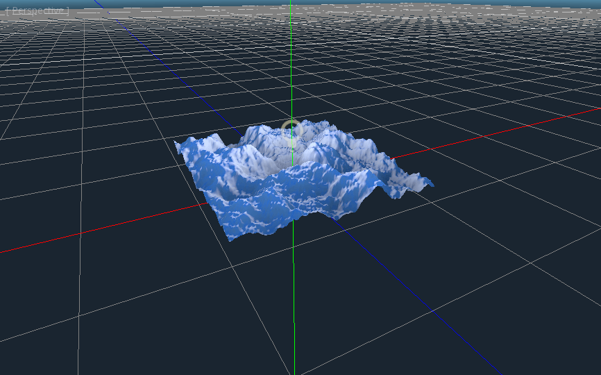
With the noise function in place we already have something that looks kind of cool. There is a lot of detail, it kind of looks hilly or mountainous.
Fragment Shader
The difference between a vertex shader and a fragment shader is that the vertex shader
runs per vertex and sets properties such as VERTEX (position) and NORMAL, while
the fragment shader runs per pixel and, most importantly, sets the ALBEDO color of the Mesh.
Now lets look at the Mesh with a regular shader instead of the wireframe. Set the viewport back to ‘Display Normal’.
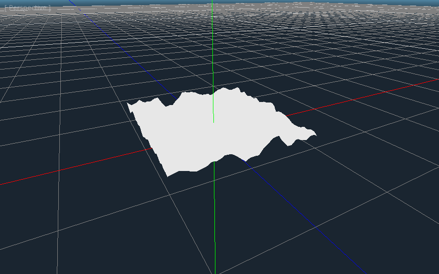
The Mesh appears completely white because the fragment shader is coloring each pixel white,
but if every pixel is white we lose detail on the Mesh. So lets color each pixel based
on the height calculated in the vertex shader. We do so by setting the COLOR variable
in the vertex shader. And by setting the ALBEDO in the fragment shader to the calculated
COLOR variable.
void vertex() {
  ...
  COLOR.xyz = vec3(height);
}

void fragment(){
  ALBEDO = COLOR.xyz;
}
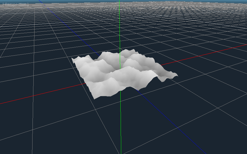
With this change we can see the detail of the Mesh, even without displaying the Mesh’s wireframe.
Uniforms
Uniform variables allow you to pass data from the game into the shader. They can
be very useful for controlling shader effects. Uniforms can be almost any
datatype that can be used in the shader. To use a uniform you declare it in
your Shader using the keyword uniform.
Lets make a uniform that changes the height of the terrain.
uniform float height_scale = 0.5;
Godot lets you initialize a uniform with a value, here height_scale is set to
0.5. You can set uniforms from gdscript by calling the function set_shader_param
on the material corresponding to the shader. The value passed from gdscript takes
precedence over the value used to initialize it in the shader.
material.set_shader_param("height_scale", 0.5)
Remember that the string passed into set_shader_param must match the name
of the uniform variable in the Shader. You can use the uniform variable anywhere
inside your Shader. Here, we will use it to set the height value instead
of arbitrarily multiplying by 0.5.
VERTEX.y += height * height_scale;
The terrain should look exactly the same, but now we have control over the height easily.
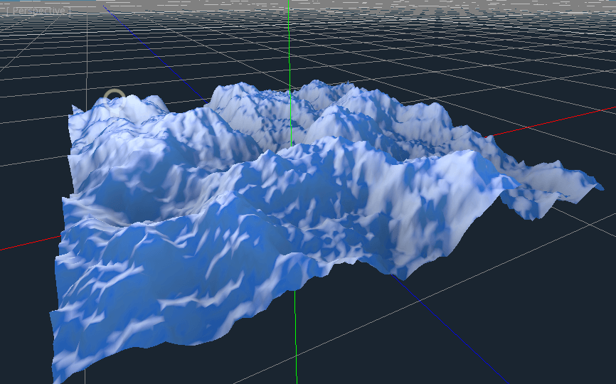
Here is the same terrain with height_scale set to 1:
And here it is with height_scale set to 0.2:
Using uniforms we can even change the value every frame to animate the height of the terrain. Combined with Tweens this can be especially useful for simple animations.
Interacting with light
As a final part of this tutorial lets try to set up the terrain to interact with light. First, we will add an OmniLight to the scene.
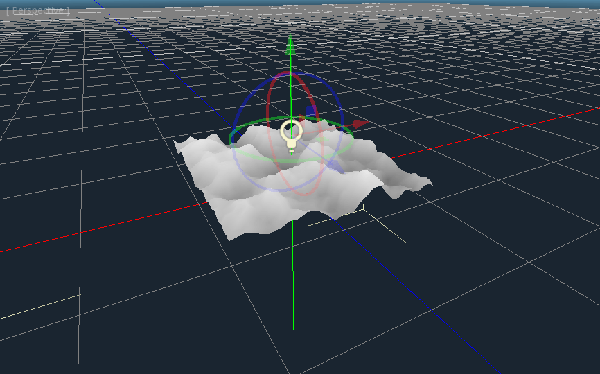
You should notice that nothing changes, this is because we set the render_mode to unshaded
at the beginning of this tutorial, lets remove that.
shader_type spatial;
//render_mode unshaded;
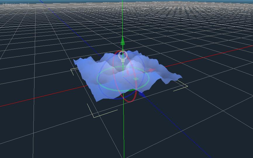
It looks slightly better now, you can see the light affecting the terrain, and it has
turned blue as a result of the sky. The problem is the light is affecting the terrain
as if it were a flat plane. This is because the light shader uses the normals of the
Mesh to calculate light. The normals are stored in the Mesh, but we are changing
the shape of the Mesh in the shader so the normals are no longer correct. To fix this
we need to recalculate the normals in the shader. Godot makes this easy for us, all we
have to do is calculate the new normal and set NORMAL to that value in the vertex shader.
With NORMAL set Godot will do all the difficult lighting calculations for us.
To calculate the normal from noise we are going to use a technique called ‘central differences’.
This is used a lot, especially in places like shadertoy, to calculate normals in shaders.
What we will do is calculate the noise at four points surrounding the vertex in the x and z directions and then calculate
the slope at the vertex from that. After all a normal is just an indicator of the slope of the
noise.
We calculate the normal with one line in the vertex shader.
vec2 e = vec2(0.01, 0.0);
vec3 normal = normalize(vec3(fbm(VERTEX.xz - e) - fbm(VERTEX.xz + e), 2.0 * e.x, fbm(VERTEX.xz - e.yx) - fbm(VERTEX.xz + e.yx)));
NORMAL = normal;
The variable e just makes it easier to add and subtract the right value from the VERTEX.
Setting e to a lower number will increase the level of detail of the normal.
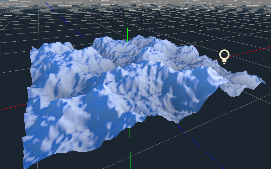
With NORMAL calculated the terrain now looks like:
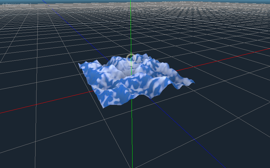
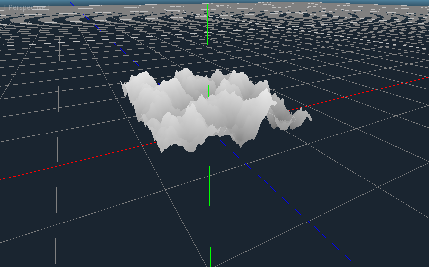
This still does not look how we want it to. The issue here is that the noise changes
faster than the vertices do. So when we calculate the normal at the point of the
VERTEX it does not align with what we see in the final Mesh. In order to fix
this we add more vertices. The below image is made with a Mesh with subdivision set
to 100.
Now we can drag the light around and the lighting will update automatically.
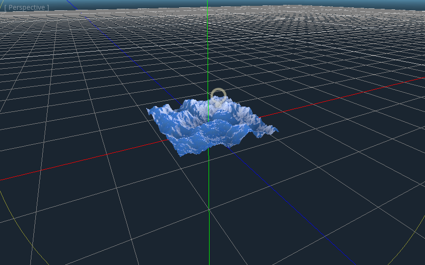
If you zoom the camera out you can see that the Mesh now looks like a small terrain.
That is everything for this tutorial. Hopefully you understand the basics of vertex
shaders in Godot. As a further exercise try changing the height_scale from gdscript,
try using different Primitive Meshes, and try making your
own functions to calculate height.
For further information on how to use shaders in Godot you should check out the Shading language page.