Attention: Here be dragons
This is the latest
(unstable) version of this documentation, which may document features
not available in or compatible with released stable versions of Godot.
Checking the stable version of the documentation...
Desenho personalizado em 2D
Introdução
Godot has nodes to draw sprites, polygons, particles, text, and many other common game development needs. However, if you need something specific not covered with the standard nodes you can make any 2D node (for example, Control or Node2D-based) draw on screen using custom commands.
O desenho personalizado em um nó 2D é realmente útil. Aqui estão alguns casos de uso:
Desenhar formas ou lógica que os nós existentes não podem fazer, como uma imagem com rastros ou um polígono animado especial.
Drawing a large number of simple objects, such as a grid or a board for a 2d game. Custom drawing avoids the overhead of using a large number of nodes, possibly lowering memory usage and improving performance.
Fazendo um controle de interface do usuário personalizado. Há muitos controles disponíveis, mas quando você tiver necessidades incomuns, provavelmente precisará de um controle personalizado.
Desenhando
Add a script to any CanvasItem derived node, like Control or Node2D. Then override the _draw() function.
extends Node2D

func _draw():
    pass  # Your draw commands here.
using Godot;

public partial class MyNode2D : Node2D
{
    public override void _Draw()
    {
        // Your draw commands here.
    }
}
Draw commands are described in the CanvasItem class reference. There are plenty of them and we will see some of them in the examples below.
Atualizando
The _draw function is only called once, and then the draw commands are cached and remembered, so further calls are unnecessary.
If re-drawing is required because a variable or something else changed,
call CanvasItem.queue_redraw
in that same node and a new _draw() call will happen.
Aqui está um exemplo um pouco mais complexo, onde temos uma variável de textura que pode ser modificada a qualquer momento e, usando um setter, ela força um redesenho da textura quando modificada:
extends Node2D

@export var texture : Texture2D:
    set(value):
        texture = value
        queue_redraw()

func _draw():
    draw_texture(texture, Vector2())
using Godot;

public partial class MyNode2D : Node2D
{
    private Texture2D _texture;

    [Export]
    public Texture2D Texture
    {
        get
        {
            return _texture;
        }

        set
        {
            _texture = value;
            QueueRedraw();
        }
    }

    public override void _Draw()
    {
        DrawTexture(_texture, new Vector2());
    }
}
Para vê-lo em ação, você pode definir a textura como o ícone do Godot no editor arrastando e soltando o icon.svg padrão da aba FileSystem para a propriedade Textura na aba do Inspetor. Ao alterar o valor da propriedade Textura enquanto o script anterior estiver em execução, a textura também será alterada automaticamente.
In some cases, we may need to redraw every frame. For this, call queue_redraw from the _process method, like this:
extends Node2D

func _draw():
    pass  # Your draw commands here.

func _process(_delta):
    queue_redraw()
using Godot;

public partial class MyNode2D : Node2D
{
    public override void _Draw()
    {
        // Your draw commands here.
    }

    public override void _Process(double delta)
    {
        QueueRedraw();
    }
}
Coordenadas e alinhamento de largura de linha
A API de desenho usa o sistema de coordenadas do CanvasItem, não necessariamente coordenadas em pixels. Isso significa que _draw() utiliza o espaço de coordenadas criado após a aplicação da transformação do CanvasItem. Além disso, você pode aplicar uma transformação personalizada sobre ela usando draw_set_transform ou draw_set_transform_matrix.
Ao usar draw_line, você deve considerar a largura da linha. Ao utilizar uma largura com valor ímpar, a posição dos pontos inicial e final deve ser ajustada em 0.5 para manter a linha centralizada, como mostrado abaixo.
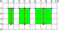
func _draw():
    draw_line(Vector2(1.5, 1.0), Vector2(1.5, 4.0), Color.GREEN, 1.0)
    draw_line(Vector2(4.0, 1.0), Vector2(4.0, 4.0), Color.GREEN, 2.0)
    draw_line(Vector2(7.5, 1.0), Vector2(7.5, 4.0), Color.GREEN, 3.0)
public override void _Draw()
{
    DrawLine(new Vector2(1.5f, 1.0f), new Vector2(1.5f, 4.0f), Colors.Green, 1.0f);
    DrawLine(new Vector2(4.0f, 1.0f), new Vector2(4.0f, 4.0f), Colors.Green, 2.0f);
    DrawLine(new Vector2(7.5f, 1.0f), new Vector2(7.5f, 4.0f), Colors.Green, 3.0f);
}
O mesmo se aplica ao método draw_rect com filled = false.
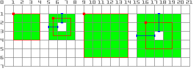
func _draw():
    draw_rect(Rect2(1.0, 1.0, 3.0, 3.0), Color.GREEN)
    draw_rect(Rect2(5.5, 1.5, 2.0, 2.0), Color.GREEN, false, 1.0)
    draw_rect(Rect2(9.0, 1.0, 5.0, 5.0), Color.GREEN)
    draw_rect(Rect2(16.0, 2.0, 3.0, 3.0), Color.GREEN, false, 2.0)
public override void _Draw()
{
    DrawRect(new Rect2(1.0f, 1.0f, 3.0f, 3.0f), Colors.Green);
    DrawRect(new Rect2(5.5f, 1.5f, 2.0f, 2.0f), Colors.Green, false, 1.0f);
    DrawRect(new Rect2(9.0f, 1.0f, 5.0f, 5.0f), Colors.Green);
    DrawRect(new Rect2(16.0f, 2.0f, 3.0f, 3.0f), Colors.Green, false, 2.0f);
}
Desenho com suavização de serrilhado
Godot offers method parameters in draw_line
to enable antialiasing, but not all custom drawing methods offer this antialiased
parameter.
Para métodos de desenho personalizados que não fornecem um parâmetro antialiased, você pode ativar o MSAA 2D em vez disso, o que afeta a renderização em todo a janela de exibição. Isso fornece antialiasing de alta qualidade, mas com um custo maior de desempenho e somente em elementos específicos. Veja 2D antialiasing para mais informações.
Aqui está uma comparação de uma linha de largura mínima (width=-1) desenhada com antialiased=false, antialiased=true e antialiased=false com MSAA 2D 2x, 4x e 8x habilitado.

Ferramentas
Drawing your own nodes might also be desired while running them in the editor. This can be used as a preview or visualization of some feature or behavior.
Para fazer isso, você pode usar a anotação tool tanto em GDScript quanto em C#. Veja o exemplo abaixo e Executando o código no editor para mais informações.
Eis um exemplo de como criar um tipo de dados personalizado:
We will now use the custom drawing functionality of the Godot Engine to draw something that Godot doesn't provide functions for. We will recreate the Godot logo but with code- only using drawing functions.
Você terá que codificar uma função para executar isso e desenhá-la você mesmo.
Nota
As instruções a seguir usam um conjunto fixo de coordenadas que pode ser muito pequeno para telas de alta resolução (maiores que 1080p). Se esse for o seu caso, e o desenho estiver muito pequeno, considere aumentar a escala da janela nas configurações do projeto em Exibição > Janela > Esticar > Escala para ajustar o projeto a uma resolução mais alta (uma escala de 2 ou 4 tende a funcionar bem).
Criando um nó de um polígono personalizado
Embora haja um nó dedicado para desenhar polígonos personalizados ( Polygon2D), vamos usar neste caso exclusivamente funções de desenho de nível inferior para combiná-los no mesmo nó e ser capaz de criar formas mais complexas mais tarde.
Primeiro, definiremos um conjunto de pontos -ou coordenadas X e Y - que formarão a base da nossa forma:
extends Node2D

var coords_head : Array = [
    [ 22.952, 83.271 ],  [ 28.385, 98.623 ],
    [ 53.168, 107.647 ], [ 72.998, 107.647 ],
    [ 99.546, 98.623 ],  [ 105.048, 83.271 ],
    [ 105.029, 55.237 ], [ 110.740, 47.082 ],
    [ 102.364, 36.104 ], [ 94.050, 40.940 ],
    [ 85.189, 34.445 ],  [ 85.963, 24.194 ],
    [ 73.507, 19.930 ],  [ 68.883, 28.936 ],
    [ 59.118, 28.936 ],  [ 54.494, 19.930 ],
    [ 42.039, 24.194 ],  [ 42.814, 34.445 ],
    [ 33.951, 40.940 ],  [ 25.637, 36.104 ],
    [ 17.262, 47.082 ],  [ 22.973, 55.237 ]
]
using Godot;

public partial class MyNode2D : Node2D
{
    private float[,] _coordsHead =
    {
        { 22.952f, 83.271f },  { 28.385f, 98.623f },
        { 53.168f, 107.647f }, { 72.998f, 107.647f },
        { 99.546f, 98.623f },  { 105.048f, 83.271f },
        { 105.029f, 55.237f }, { 110.740f, 47.082f },
        { 102.364f, 36.104f }, { 94.050f, 40.940f },
        { 85.189f, 34.445f },  { 85.963f, 24.194f },
        { 73.507f, 19.930f },  { 68.883f, 28.936f },
        { 59.118f, 28.936f },  { 54.494f, 19.930f },
        { 42.039f, 24.194f },  { 42.814f, 34.445f },
        { 33.951f, 40.940f },  { 25.637f, 36.104f },
        { 17.262f, 47.082f },  { 22.973f, 55.237f }
    };
}
Este formato, enquanto compacto, não é aquele que Godot entende desenhar um polígono. Em um cenário diferente, poderíamos ter que carregar essas coordenadas de um arquivo ou calcular as posições enquanto o aplicativo está sendo executado, então alguma transformação pode ser necessária.
Para transformar essas coordenadas no formato certo, criaremos um novo método float_array_to_Vector2Array(). Então vamos substituir a função _ready(), que Godot vai chamar apenas uma vez - no início da execução- para carregar essas coordenadas em uma variável:
var head : PackedVector2Array

func float_array_to_Vector2Array(coords : Array) -> PackedVector2Array:
    # Convert the array of floats into a PackedVector2Array.
    var array : PackedVector2Array = []
    for coord in coords:
        array.append(Vector2(coord[0], coord[1]))
    return array

func _ready():
    head = float_array_to_Vector2Array(coords_head);
private Vector2[] _head;

private Vector2[] FloatArrayToVector2Array(float[,] coords)
{
    // Convert the array of floats into an array of Vector2.
    int size = coords.GetUpperBound(0);
    Vector2[] array = new Vector2[size + 1];
    for (int i = 0; i <= size; i++)
    {
        array[i] = new Vector2(coords[i, 0], coords[i, 1]);
    }
    return array;
}

public override void _Ready()
{
    _head = FloatArrayToVector2Array(_coordsHead);
}
Para finalmente desenhar nossa primeira forma, vamos usar o método draw_polygon e passar os pontos (como uma matriz de coordenadas Vector2) e sua cor, como esta:
func _draw():
    # We are going to paint with this color.
    var godot_blue : Color = Color("478cbf")
    # We pass the PackedVector2Array to draw the shape.
    draw_polygon(head, [ godot_blue ])
public override void _Draw()
{
    // We are going to paint with this color.
    Color godotBlue = new Color("478cbf");
    // We pass the array of Vector2 to draw the shape.
    DrawPolygon(_head, [godotBlue]);
}
Ao executá-lo você deve ver algo assim:
Note a parte inferior do logotipo parece segmentada - isto é porque uma baixa quantidade de pontos foram usados para definir essa parte. Para simular uma curva lisa, poderíamos adicionar mais pontos ao nosso array, ou talvez usar uma função matemática para interpor uma curva e criar uma forma lisa do código (ver example 2).
Os polígonos sempre conectam seu último ponto definido ao seu primeiro a fim de ter uma forma fechada.
Desenhando linhas conectadas
Desenhar uma sequência de linhas conectadas que não se fecham para formar um polígono é muito semelhante ao método anterior. Usaremos um conjunto de linhas conectadas para desenhar a boca do logotipo do Godot.
Primeiro, vamos definir a lista de coordenadas que formam a forma da boca, assim:
var coords_mouth = [
    [ 22.817, 81.100 ], [ 38.522, 82.740 ],
    [ 39.001, 90.887 ], [ 54.465, 92.204 ],
    [ 55.641, 84.260 ], [ 72.418, 84.177 ],
    [ 73.629, 92.158 ], [ 88.895, 90.923 ],
    [ 89.556, 82.673 ], [ 105.005, 81.100 ]
]
private float[,] _coordsMouth =
{
    { 22.817f, 81.100f }, { 38.522f, 82.740f },
    { 39.001f, 90.887f }, { 54.465f, 92.204f },
    { 55.641f, 84.260f }, { 72.418f, 84.177f },
    { 73.629f, 92.158f }, { 88.895f, 90.923f },
    { 89.556f, 82.673f }, { 105.005f, 81.100f }
};
Vamos carregar essas coordenadas em uma variável e definir uma variável adicional com a espessura da linha configurável:
var mouth : PackedVector2Array
var _mouth_width : float = 4.4

func _ready():
    head = float_array_to_Vector2Array(coords_head);
    mouth = float_array_to_Vector2Array(coords_mouth);
private Vector2[] _mouth;
private float _mouthWidth = 4.4f;

public override void _Ready()
{
    _head = FloatArrayToVector2Array(_coordsHead);
    _mouth = FloatArrayToVector2Array(_coordsMouth);
}
E finalmente usaremos o método draw_polyline para realmente desenhar a linha, assim:
func _draw():
    # We will use white to draw the line.
    var white : Color = Color.WHITE
    var godot_blue : Color = Color("478cbf")

    draw_polygon(head, [ godot_blue ])

    # We draw the while line on top of the previous shape.
    draw_polyline(mouth, white, _mouth_width)
public override void _Draw()
{
    // We will use white to draw the line.
    Color white = Colors.White;
    Color godotBlue = new Color("478cbf");

    DrawPolygon(_head, [godotBlue]);

    // We draw the while line on top of the previous shape.
    DrawPolyline(_mouth, white, _mouthWidth);
}
Você deve obter a seguinte saída:
Unlike draw_polygon(), polylines can only have a single unique color
for all its points (the second argument). This method has 2 additional
arguments: the width of the line (which is as small as possible by default)
and enabling or disabling the antialiasing (it is disabled by default).
A ordem das chamadas _draw é importante - como que com as posições dos Nós na hierarquia da árvore, as diferentes formas serão desenhadas de cima para baixo, resultando nas formas mais recentes que se escondem mais cedo se eles se sobrepõem. Neste caso queremos a boca desenhada sobre a cabeça, então colocamos depois.
Observe como podemos definir cores de maneiras diferentes, seja com um código hexadecimal ou um nome de cor predefinido. Confira a classe Color para outras constantes e formas de definir Cores.
Desenhando Círculos
Para criar os olhos, vamos adicionar 4 chamadas adicionais para desenhar as formas dos olhos, em diferentes tamanhos, cores e posições.
To draw a circle, you position it based on its center using the draw_circle method. The first parameter is a Vector2 with the coordinates of its center, the second is its radius, and the third is its color:
func _draw():
    var white : Color = Color.WHITE
    var godot_blue : Color = Color("478cbf")
    var grey : Color = Color("414042")

    draw_polygon(head, [ godot_blue ])
    draw_polyline(mouth, white, _mouth_width)

    # Four circles for the 2 eyes: 2 white, 2 grey.
    draw_circle(Vector2(42.479, 65.4825), 9.3905, white)
    draw_circle(Vector2(85.524, 65.4825), 9.3905, white)
    draw_circle(Vector2(43.423, 65.92), 6.246, grey)
    draw_circle(Vector2(84.626, 66.008), 6.246, grey)
public override void _Draw()
{
    Color white = Colors.White;
    Color godotBlue = new Color("478cbf");
    Color grey = new Color("414042");

    DrawPolygon(_head, [godotBlue]);
    DrawPolyline(_mouth, white, _mouthWidth);

    // Four circles for the 2 eyes: 2 white, 2 grey.
    DrawCircle(new Vector2(42.479f, 65.4825f), 9.3905f, white);
    DrawCircle(new Vector2(85.524f, 65.4825f), 9.3905f, white);
    DrawCircle(new Vector2(43.423f, 65.92f), 6.246f, grey);
    DrawCircle(new Vector2(84.626f, 66.008f), 6.246f, grey);
}
Ao executá-lo, você deve ter algo assim:
Para arcos parciais, não preenchidos (porções de uma forma círculo entre certos ângulos arbitrários), você pode usar o método draw_arc.
Desenhando linhas
Para desenhar a forma final (o nariz) usaremos uma linha para aproximá-la.
draw_line pode ser usado para desenhar um único segmento fornecendo suas coordenadas de início e fim como argumentos, como este:
func _draw():
    var white : Color = Color.WHITE
    var godot_blue : Color = Color("478cbf")
    var grey : Color = Color("414042")

    draw_polygon(head, [ godot_blue ])
    draw_polyline(mouth, white, _mouth_width)
    draw_circle(Vector2(42.479, 65.4825), 9.3905, white)
    draw_circle(Vector2(85.524, 65.4825), 9.3905, white)
    draw_circle(Vector2(43.423, 65.92), 6.246, grey)
    draw_circle(Vector2(84.626, 66.008), 6.246, grey)

    # Draw a short but thick white vertical line for the nose.
    draw_line(Vector2(64.273, 60.564), Vector2(64.273, 74.349), white, 5.8)
public override void _Draw()
{
    Color white = Colors.White;
    Color godotBlue = new Color("478cbf");
    Color grey = new Color("414042");

    DrawPolygon(_head, [godotBlue]);
    DrawPolyline(_mouth, white, _mouthWidth);
    DrawCircle(new Vector2(42.479f, 65.4825f), 9.3905f, white);
    DrawCircle(new Vector2(85.524f, 65.4825f), 9.3905f, white);
    DrawCircle(new Vector2(43.423f, 65.92f), 6.246f, grey);
    DrawCircle(new Vector2(84.626f, 66.008f), 6.246f, grey);

    // Draw a short but thick white vertical line for the nose.
    DrawLine(new Vector2(64.273f, 60.564f), new Vector2(64.273f, 74.349f),
             white, 5.8f);
}
Agora você deve ser capaz de ver a seguinte forma na tela:
Note que se várias linhas não conectadas forem desenhadas ao mesmo tempo, você pode obter desempenho adicional desenhando todas elas em uma única chamada, usando o método draw_multiline.
Desenhando texto
While using the Label Node is the most common way to add text to your application, the low-level _draw function includes functionality to add text to your custom Node drawing. We will use it to add the name "GODOT" under the robot head.
Vamos usar o método draw_string para fazê-lo, assim:
var default_font : Font = ThemeDB.fallback_font;

func _draw():
    var white : Color = Color.WHITE
    var godot_blue : Color = Color("478cbf")
    var grey : Color = Color("414042")

    draw_polygon(head, [ godot_blue ])
    draw_polyline(mouth, white, _mouth_width)
    draw_circle(Vector2(42.479, 65.4825), 9.3905, white)
    draw_circle(Vector2(85.524, 65.4825), 9.3905, white)
    draw_circle(Vector2(43.423, 65.92), 6.246, grey)
    draw_circle(Vector2(84.626, 66.008), 6.246, grey)
    draw_line(Vector2(64.273, 60.564), Vector2(64.273, 74.349), white, 5.8)

    # Draw GODOT text below the logo with the default font, size 22.
    draw_string(default_font, Vector2(20, 130), "GODOT",
                HORIZONTAL_ALIGNMENT_CENTER, 90, 22)
private Font _defaultFont = ThemeDB.FallbackFont;

public override void _Draw()
{
    Color white = Colors.White;
    Color godotBlue = new Color("478cbf");
    Color grey = new Color("414042");

    DrawPolygon(_head, [godotBlue]);
    DrawPolyline(_mouth, white, _mouthWidth);
    DrawCircle(new Vector2(42.479f, 65.4825f), 9.3905f, white);
    DrawCircle(new Vector2(85.524f, 65.4825f), 9.3905f, white);
    DrawCircle(new Vector2(43.423f, 65.92f), 6.246f, grey);
    DrawCircle(new Vector2(84.626f, 66.008f), 6.246f, grey);
    DrawLine(new Vector2(64.273f, 60.564f), new Vector2(64.273f, 74.349f),
             white, 5.8f);

    // Draw GODOT text below the logo with the default font, size 22.
    DrawString(_defaultFont, new Vector2(20f, 130f), "GODOT",
               HorizontalAlignment.Center, 90, 22);
}
Aqui nós primeiro carregamos a variável defaultFont a fonte padrão configurada no tema(uma personalizada pode ser definida no lugar) e então passamos os seguintes parâmetros: fonte, posição, texto, alinhamento horizontal, largura e tamanho da fonte.
Você deve ver o seguinte em sua tela:
Parâmetros adicionais, bem como outros métodos relacionados ao texto e caracteres podem ser encontrados na referência de classe CanvasItem.
Mostrar o desenho durante a edição
Enquanto o código até agora é capaz de desenhar o logotipo em uma janela em execução, ele não aparecerá na view 2D no editor. Em certos casos, você também gostaria de mostrar seu Node2D personalizado ou controle no editor, posicionar e dimensioná-lo adequadamente, como a maioria dos outros nós fazem.
Para mostrar o logotipo diretamente no editor (sem executá-lo), você pode usar o @tool anotação para solicitar o desenho personalizado do nó também aparecer enquanto edita, assim:
@tool
extends Node2D
using Godot;

[Tool]
public partial class MyNode2D : Node2D
Você precisará salvar sua cena, refazer a build seu projeto (apenas para C#) e recarregar a cena atual manualmente na opção menu Scene > Recarregue Saved Scene para refrescar o nó atual na view 2D da primeira vez que você adicionar ou remover a anotação @tool.
Animação
Se quiséssemos fazer a mudança de forma personalizada no tempo de execução, poderíamos modificar os métodos chamados ou seus argumentos no tempo de execução, ou aplicar uma transformação.
Por exemplo, se quisermos a forma personalizada que acabamos de projetar para girar, poderíamos adicionar a seguinte variável e código aos métodos _ready e _process:
extends Node2D

@export var rotation_speed : float = 1  # In radians per second.

func _ready():
    rotation = 0
    ...

func _process(delta: float):
    rotation -= rotation_speed * delta
[Export]
public float RotationSpeed { get; set; } = 1.0f;  // In radians per second.

public override void _Ready()
{
    Rotation = 0;
    ...
}

public override void _Process(double delta)
{
    Rotation -= RotationSpeed * (float)delta;
}
O problema com o código acima é que porque criamos os pontos aproximadamente em um retângulo a partir do canto superior esquerdo, a coordenada (0, 0)` e estendendo-se para a direita e para baixo, vemos que a rotação é feita usando o canto superior esquerdo como pivô. Uma mudança de posição de transformação no nó não nos ajudará aqui, pois a transformação de rotação é aplicada primeiro.
Embora pudéssemos reescrever todas as coordenadas dos pontos para serem centradas em torno de (0, 0), incluindo coordenadas negativas, isso seria muito trabalho.
Uma maneira possível de trabalhar em torno disso é usar o método de nível mais baixo draw_set_transform para corrigir este problema, traduzindo todos os pontos no próprio espaço do CanvasItem, e depois movendo-o de volta para o seu lugar original com um nó regular transforma, tanto no editor ou no código, como este:
func _ready():
    rotation = 0
    position = Vector2(60, 60)
    ...

func _draw():
    draw_set_transform(Vector2(-60, -60))
    ...
public override void _Ready()
{
    Rotation = 0;
    Position = new Vector2(60, 60);
    ...
}

public override void _Draw()
{
    DrawSetTransform(new Vector2(-60.0f, -60.0f));
    ...
}
Este é o resultado, girando em torno de um pivô agora em (60, 60):

Se o que queríamos animar era uma propriedade dentro da chamada _draw(), devemos lembrar de chamar queue_redraw() para forçar uma atualização, como de outra forma não seria atualizado na tela.
Por exemplo, é assim que podemos fazer o robô parecer abrir e fechar a boca, alterando a largura de sua linha da boca seguir uma curva sinusoidal (sin):
var _mouth_width : float = 4.4
var _max_width : float = 7
var _time : float = 0

func _process(delta : float):
    _time += delta
    _mouth_width = abs(sin(_time) * _max_width)
    queue_redraw()

func _draw():
    ...
    draw_polyline(mouth, white, _mouth_width)
    ...
private float _mouthWidth = 4.4f;
private float _maxWidth = 7f;
private float _time = 0f;

public override void _Process(double delta)
{
    _time += (float)delta;
    _mouthWidth = Mathf.Abs(Mathf.Sin(_time) * _maxWidth);
    QueueRedraw();
}

public override void _Draw()
{
    ...
    DrawPolyline(_mouth, white, _mouthWidth);
    ...
}
Vai parecer um pouco assim quando executar:

Observe que _mouth_width é uma propriedade definida pelo usuário como qualquer outra, e ela, ou qualquer outra usada como argumento de desenho, pode ser animada utilizando métodos mais padrão e de alto nível, como um nó Tween ou AnimationPlayer. A única diferença é que é necessário chamar queue_redraw() para aplicar essas mudanças e fazer com que elas sejam exibidas na tela.
Example 2: drawing a dynamic line
O exemplo anterior foi útil para aprender como desenhar e modificar nós com formas e animações personalizadas. Isso pode ter algumas vantagens, como o uso de coordenadas e vetores exatos para o desenho, em vez de bitmaps – o que significa que eles escalarão bem quando transformados na tela. Em alguns casos, resultados semelhantes podem ser alcançados compondo funcionalidades de nível mais alto com nós como sprites ou AnimatedSprites carregando recursos SVG (que também são imagens definidas com vetores) e o nó AnimationPlayer.
Em outros casos isso não será possível, pois não saberemos qual será a representação gráfica resultante antes de executar o código. Aqui veremos como desenhar uma linha dinâmica cujas coordenadas não são conhecidas previamente e são afetadas pela entrada do usuário.
Desenhando uma linha reta entre 2 pontos
Vamos supor que queremos desenhar uma linha reta entre 2 pontos, o primeiro será fixado no canto superior esquerdo (0, 0) e o segundo será definido pela posição do cursor na tela.
Poderíamos traçar uma linha dinâmica entre esses dois pontos assim:
extends Node2D

var point1 : Vector2 = Vector2(0, 0)
var width : int = 10
var color : Color = Color.GREEN

var _point2 : Vector2

func _process(_delta):
    var mouse_position = get_viewport().get_mouse_position()
    if mouse_position != _point2:
        _point2 = mouse_position
        queue_redraw()

func _draw():
    draw_line(point1, _point2, color, width)
using Godot;
using System;

public partial class MyNode2DLine : Node2D
{
    public Vector2 Point1 { get; set; } = new Vector2(0f, 0f);
    public int Width { get; set; } = 10;
    public Color Color { get; set; } = Colors.Green;

    private Vector2 _point2;

    public override void _Process(double delta)
    {
        Vector2 mousePosition = GetViewport().GetMousePosition();
        if (mousePosition != _point2)
        {
            _point2 = mousePosition;
            QueueRedraw();
        }
    }

    public override void _Draw()
    {
        DrawLine(Point1, _point2, Color, Width);
    }
}
Neste exemplo, obtemos a posição do mouse na janela de exibição padrão a cada frame com o método get_mouse_position. Se a posição tiver mudado desde o último pedido de desenho (uma pequena otimização para evitar redesenhar a cada frame), agendamos um redesenho. Nosso método _draw() possui somente uma linha: solicitar o desenho de uma linha verde com 10 pixels de largura entre o canto superior esquerdo e a posição obtida.
A largura, cor e posição do ponto inicial podem ser configuradas com as propriedades correspondentes.
It should look like this when run:

Desenhando um arco entre 2 pontos
O exemplo acima funciona, mas talvez queiramos unir esses dois pontos com uma forma ou função diferente, que não seja uma linha reta.
Vamos tentar agora criar um arco (uma parte de uma circunferência) entre os dois pontos.
Exportar o ponto inicial da linha, segmentos, largura, cor e antialiasing nos permitirá modificar essas propriedades facilmente, diretamente do painel do Inspetor do editor:
extends Node2D

@export var point1 : Vector2 = Vector2(0, 0)
@export_range(1, 1000) var segments : int = 100
@export var width : int = 10
@export var color : Color = Color.GREEN
@export var antialiasing : bool = false

var _point2 : Vector2
using Godot;
using System;

public partial class MyNode2DLine : Node2D
{
    [Export]
    public Vector2 Point1 { get; set; } = new Vector2(0f, 0f);
    [Export]
    public float Length { get; set; } = 350f;
    [Export(PropertyHint.Range, "1,1000,")]
    public int Segments { get; set; } = 100;
    [Export]
    public int Width { get; set; } = 10;
    [Export]
    public Color Color { get; set; } = Colors.Green;
    [Export]
    public bool AntiAliasing { get; set; } = false;

    private Vector2 _point2;
}

Para desenhar o arco, podemos usar o método draw_arc. Existem muitos arcos que passam por 2 pontos, então, para este exemplo, escolheremos o semicírculo cujo centro está no ponto médio entre os 2 pontos iniciais.
O cálculo deste arco será mais complexo do que no caso da reta:
func _draw():
    # Average points to get center.
    var center : Vector2 = Vector2((_point2.x + point1.x) / 2,
                                   (_point2.y + point1.y) / 2)
    # Calculate the rest of the arc parameters.
    var radius : float = point1.distance_to(_point2) / 2
    var start_angle : float = (_point2 - point1).angle()
    var end_angle : float = (point1 - _point2).angle()
    if end_angle < 0:  # end_angle is likely negative, normalize it.
        end_angle += TAU

    # Finally, draw the arc.
    draw_arc(center, radius, start_angle, end_angle, segments, color,
             width, antialiasing)
public override void _Draw()
{
    // Average points to get center.
    Vector2 center = new Vector2((_point2.X + Point1.X) / 2.0f,
                                    (_point2.Y + Point1.Y) / 2.0f);
    // Calculate the rest of the arc parameters.
    float radius = Point1.DistanceTo(_point2) / 2.0f;
    float startAngle = (_point2 - Point1).Angle();
    float endAngle = (Point1 - _point2).Angle();
    if (endAngle < 0.0f)  // endAngle is likely negative, normalize it.
    {
        endAngle += Mathf.Tau;
    }

    // Finally, draw the arc.
    DrawArc(center, radius, startAngle, endAngle, Segments, Color,
            Width, AntiAliasing);
}
O centro do semicírculo será o ponto médio entre os dois pontos. O raio será metade da distância entre os dois pontos. Os ângulos inicial e final serão os ângulos do vetor de point1 para point2 e vice-versa. Note que foi necessário normalizar o end_angle para valores positivos, pois se end_angle for menor que start_angle, o arco será desenhado no sentido anti-horário, o que não queremos neste caso (o arco ficaria de cabeça para baixo).
O resultado deve ser algo assim, com o arco descendo e entre os pontos:

Sinta-se à vontade para experimentar os parâmetros no inspetor para obter resultados diferentes: altere a cor, a largura, o antialiasing e aumente o número de segmentos para melhorar a suavidade da curva, ao custo de desempenho adicional.