Attention: Here be dragons
This is the latest
(unstable) version of this documentation, which may document features
not available in or compatible with released stable versions of Godot.
Checking the stable version of the documentation...
2Dカスタム描画
はじめに
Godot has nodes to draw sprites, polygons, particles, text, and many other common game development needs. However, if you need something specific not covered with the standard nodes you can make any 2D node (for example, Control or Node2D-based) draw on screen using custom commands.
Custom drawing in a 2D node is really useful. Here are some use cases:
Drawing shapes or logic that existing nodes can't do, such as an image with trails or a special animated polygon.
Drawing a large number of simple objects, such as a grid or a board for a 2d game. Custom drawing avoids the overhead of using a large number of nodes, possibly lowering memory usage and improving performance.
Making a custom UI control. There are plenty of controls available, but when you have unusual needs, you will likely need a custom control.
描画
Add a script to any CanvasItem derived node, like Control or Node2D. Then override the _draw() function.
extends Node2D

func _draw():
    pass  # Your draw commands here.
using Godot;

public partial class MyNode2D : Node2D
{
    public override void _Draw()
    {
        // Your draw commands here.
    }
}
Draw commands are described in the CanvasItem class reference. There are plenty of them and we will see some of them in the examples below.
描画の更新
The _draw function is only called once, and then the draw commands are cached and remembered, so further calls are unnecessary.
If re-drawing is required because a variable or something else changed,
call CanvasItem.queue_redraw
in that same node and a new _draw() call will happen.
Here is a little more complex example, where we have a texture variable that can be modified at any time, and using a setter, it forces a redraw of the texture when modified:
extends Node2D

@export var texture : Texture2D:
    set(value):
        texture = value
        queue_redraw()

func _draw():
    draw_texture(texture, Vector2())
using Godot;

public partial class MyNode2D : Node2D
{
    private Texture2D _texture;

    [Export]
    public Texture2D Texture
    {
        get
        {
            return _texture;
        }

        set
        {
            _texture = value;
            QueueRedraw();
        }
    }

    public override void _Draw()
    {
        DrawTexture(_texture, new Vector2());
    }
}
To see it in action, you can set the texture to be the Godot icon on the
editor by dragging and dropping the default icon.svg from the
FileSystem tab to the Texture property on the Inspector tab.
When changing the Texture property value while the previous script is
running, the texture will also change automatically.
In some cases, we may need to redraw every frame. For this, call queue_redraw from the _process method, like this:
extends Node2D

func _draw():
    pass  # Your draw commands here.

func _process(_delta):
    queue_redraw()
using Godot;

public partial class MyNode2D : Node2D
{
    public override void _Draw()
    {
        // Your draw commands here.
    }

    public override void _Process(double delta)
    {
        QueueRedraw();
    }
}
Coordinates and line width alignment
The drawing API uses the CanvasItem's coordinate system, not necessarily pixel
coordinates. This means _draw() uses the coordinate space created after
applying the CanvasItem's transform. Additionally, you can apply a custom
transform on top of it by using
draw_set_transform or
draw_set_transform_matrix.
When using draw_line, you should
consider the width of the line. When using a width that is an odd size, the
position of the start and end points should be shifted by 0.5 to keep the
line centered, as shown below.
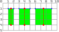
func _draw():
    draw_line(Vector2(1.5, 1.0), Vector2(1.5, 4.0), Color.GREEN, 1.0)
    draw_line(Vector2(4.0, 1.0), Vector2(4.0, 4.0), Color.GREEN, 2.0)
    draw_line(Vector2(7.5, 1.0), Vector2(7.5, 4.0), Color.GREEN, 3.0)
public override void _Draw()
{
    DrawLine(new Vector2(1.5f, 1.0f), new Vector2(1.5f, 4.0f), Colors.Green, 1.0f);
    DrawLine(new Vector2(4.0f, 1.0f), new Vector2(4.0f, 4.0f), Colors.Green, 2.0f);
    DrawLine(new Vector2(7.5f, 1.0f), new Vector2(7.5f, 4.0f), Colors.Green, 3.0f);
}
The same applies to the draw_rect
method with filled = false.
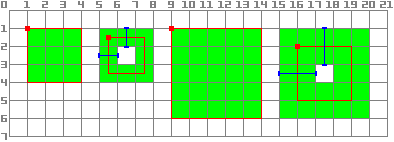
func _draw():
    draw_rect(Rect2(1.0, 1.0, 3.0, 3.0), Color.GREEN)
    draw_rect(Rect2(5.5, 1.5, 2.0, 2.0), Color.GREEN, false, 1.0)
    draw_rect(Rect2(9.0, 1.0, 5.0, 5.0), Color.GREEN)
    draw_rect(Rect2(16.0, 2.0, 3.0, 3.0), Color.GREEN, false, 2.0)
public override void _Draw()
{
    DrawRect(new Rect2(1.0f, 1.0f, 3.0f, 3.0f), Colors.Green);
    DrawRect(new Rect2(5.5f, 1.5f, 2.0f, 2.0f), Colors.Green, false, 1.0f);
    DrawRect(new Rect2(9.0f, 1.0f, 5.0f, 5.0f), Colors.Green);
    DrawRect(new Rect2(16.0f, 2.0f, 3.0f, 3.0f), Colors.Green, false, 2.0f);
}
Antialiased drawing
Godot offers method parameters in draw_line
to enable antialiasing, but not all custom drawing methods offer this antialiased
parameter.
For custom drawing methods that don't provide an antialiased parameter,
you can enable 2D MSAA instead, which affects rendering in the entire viewport.
This provides high-quality antialiasing, but a higher performance cost and only
on specific elements. See 2D antialiasing for more information.
Here is a comparison of a line of minimal width (width=-1) drawn with
antialiased=false, antialiased=true, and antialiased=false with
2D MSAA 2x, 4x, and 8x enabled.

ツール
Drawing your own nodes might also be desired while running them in the editor. This can be used as a preview or visualization of some feature or behavior.
To do this, you can use the tool annotation on both GDScript and C#. See the example below and エディタでコードを実行する for more information.
Example 1: drawing a custom shape
We will now use the custom drawing functionality of the Godot Engine to draw something that Godot doesn't provide functions for. We will recreate the Godot logo but with code- only using drawing functions.
You will have to code a function to perform this and draw it yourself.
注釈
The following instructions use a fixed set of coordinates that could be too small for high resolution screens (larger than 1080p). If that is your case, and the drawing is too small consider increasing your window scale in the project setting Display > Window > Stretch > Scale to adjust the project to a higher resolution (a 2 or 4 scale tends to work well).
Drawing a custom polygon shape
While there is a dedicated node to draw custom polygons ( Polygon2D), we will use in this case exclusively lower level drawing functions to combine them on the same node and be able to create more complex shapes later on.
First, we will define a set of points -or X and Y coordinates- that will form the base of our shape:
extends Node2D

var coords_head : Array = [
    [ 22.952, 83.271 ],  [ 28.385, 98.623 ],
    [ 53.168, 107.647 ], [ 72.998, 107.647 ],
    [ 99.546, 98.623 ],  [ 105.048, 83.271 ],
    [ 105.029, 55.237 ], [ 110.740, 47.082 ],
    [ 102.364, 36.104 ], [ 94.050, 40.940 ],
    [ 85.189, 34.445 ],  [ 85.963, 24.194 ],
    [ 73.507, 19.930 ],  [ 68.883, 28.936 ],
    [ 59.118, 28.936 ],  [ 54.494, 19.930 ],
    [ 42.039, 24.194 ],  [ 42.814, 34.445 ],
    [ 33.951, 40.940 ],  [ 25.637, 36.104 ],
    [ 17.262, 47.082 ],  [ 22.973, 55.237 ]
]
using Godot;

public partial class MyNode2D : Node2D
{
    private float[,] _coordsHead =
    {
        { 22.952f, 83.271f },  { 28.385f, 98.623f },
        { 53.168f, 107.647f }, { 72.998f, 107.647f },
        { 99.546f, 98.623f },  { 105.048f, 83.271f },
        { 105.029f, 55.237f }, { 110.740f, 47.082f },
        { 102.364f, 36.104f }, { 94.050f, 40.940f },
        { 85.189f, 34.445f },  { 85.963f, 24.194f },
        { 73.507f, 19.930f },  { 68.883f, 28.936f },
        { 59.118f, 28.936f },  { 54.494f, 19.930f },
        { 42.039f, 24.194f },  { 42.814f, 34.445f },
        { 33.951f, 40.940f },  { 25.637f, 36.104f },
        { 17.262f, 47.082f },  { 22.973f, 55.237f }
    };
}
This format, while compact, is not the one that Godot understands to draw a polygon. In a different scenario we could have to load these coordinates from a file or calculate the positions while the application is running, so some transformation may be needed.
To transform these coordinates into the right format, we will create a new
method float_array_to_Vector2Array(). Then we will override the _ready()
function, which Godot will call only once -at the start of the execution-
to load those coordinates into a variable:
var head : PackedVector2Array

func float_array_to_Vector2Array(coords : Array) -> PackedVector2Array:
    # Convert the array of floats into a PackedVector2Array.
    var array : PackedVector2Array = []
    for coord in coords:
        array.append(Vector2(coord[0], coord[1]))
    return array

func _ready():
    head = float_array_to_Vector2Array(coords_head);
private Vector2[] _head;

private Vector2[] FloatArrayToVector2Array(float[,] coords)
{
    // Convert the array of floats into an array of Vector2.
    int size = coords.GetUpperBound(0);
    Vector2[] array = new Vector2[size + 1];
    for (int i = 0; i <= size; i++)
    {
        array[i] = new Vector2(coords[i, 0], coords[i, 1]);
    }
    return array;
}

public override void _Ready()
{
    _head = FloatArrayToVector2Array(_coordsHead);
}
To finally draw our first shape, we will use the method draw_polygon and pass the points (as an array of Vector2 coordinates) and its color, like this:
func _draw():
    # We are going to paint with this color.
    var godot_blue : Color = Color("478cbf")
    # We pass the PackedVector2Array to draw the shape.
    draw_polygon(head, [ godot_blue ])
public override void _Draw()
{
    // We are going to paint with this color.
    Color godotBlue = new Color("478cbf");
    // We pass the array of Vector2 to draw the shape.
    DrawPolygon(_head, [godotBlue]);
}
When running it you should see something like this:
Note the lower part of the logo looks segmented- this is because a low amount of points were used to define that part. To simulate a smooth curve, we could add more points to our array, or maybe use a mathematical function to interpolate a curve and create a smooth shape from code (see example 2).
Polygons will always connect its last defined point to its first one in order to have a closed shape.
Drawing connected lines
Drawing a sequence of connected lines that don't close down to form a polygon is very similar to the previous method. We will use a connected set of lines to draw Godot's logo mouth.
First, we will define the list of coordinates that form the mouth shape, like this:
var coords_mouth = [
    [ 22.817, 81.100 ], [ 38.522, 82.740 ],
    [ 39.001, 90.887 ], [ 54.465, 92.204 ],
    [ 55.641, 84.260 ], [ 72.418, 84.177 ],
    [ 73.629, 92.158 ], [ 88.895, 90.923 ],
    [ 89.556, 82.673 ], [ 105.005, 81.100 ]
]
private float[,] _coordsMouth =
{
    { 22.817f, 81.100f }, { 38.522f, 82.740f },
    { 39.001f, 90.887f }, { 54.465f, 92.204f },
    { 55.641f, 84.260f }, { 72.418f, 84.177f },
    { 73.629f, 92.158f }, { 88.895f, 90.923f },
    { 89.556f, 82.673f }, { 105.005f, 81.100f }
};
We will load these coordinates into a variable and define an additional variable with the configurable line thickness:
var mouth : PackedVector2Array
var _mouth_width : float = 4.4

func _ready():
    head = float_array_to_Vector2Array(coords_head);
    mouth = float_array_to_Vector2Array(coords_mouth);
private Vector2[] _mouth;
private float _mouthWidth = 4.4f;

public override void _Ready()
{
    _head = FloatArrayToVector2Array(_coordsHead);
    _mouth = FloatArrayToVector2Array(_coordsMouth);
}
And finally we will use the method draw_polyline to actually draw the line, like this:
func _draw():
    # We will use white to draw the line.
    var white : Color = Color.WHITE
    var godot_blue : Color = Color("478cbf")

    draw_polygon(head, [ godot_blue ])

    # We draw the while line on top of the previous shape.
    draw_polyline(mouth, white, _mouth_width)
public override void _Draw()
{
    // We will use white to draw the line.
    Color white = Colors.White;
    Color godotBlue = new Color("478cbf");

    DrawPolygon(_head, [godotBlue]);

    // We draw the while line on top of the previous shape.
    DrawPolyline(_mouth, white, _mouthWidth);
}
You should get the following output:
Unlike draw_polygon(), polylines can only have a single unique color
for all its points (the second argument). This method has 2 additional
arguments: the width of the line (which is as small as possible by default)
and enabling or disabling the antialiasing (it is disabled by default).
The order of the _draw calls is important- like with the Node positions on
the tree hierarchy, the different shapes will be drawn from top to bottom,
resulting in the latest shapes hiding earlier ones if they overlap. In this
case we want the mouth drawn over the head, so we put it afterwards.
Notice how we can define colors in different ways, either with a hexadecimal code or a predefined color name. Check the class Color for other constants and ways to define Colors.
Drawing circles
To create the eyes, we are going to add 4 additional calls to draw the eye shapes, in different sizes, colors and positions.
To draw a circle, you position it based on its center using the draw_circle method. The first parameter is a Vector2 with the coordinates of its center, the second is its radius, and the third is its color:
func _draw():
    var white : Color = Color.WHITE
    var godot_blue : Color = Color("478cbf")
    var grey : Color = Color("414042")

    draw_polygon(head, [ godot_blue ])
    draw_polyline(mouth, white, _mouth_width)

    # Four circles for the 2 eyes: 2 white, 2 grey.
    draw_circle(Vector2(42.479, 65.4825), 9.3905, white)
    draw_circle(Vector2(85.524, 65.4825), 9.3905, white)
    draw_circle(Vector2(43.423, 65.92), 6.246, grey)
    draw_circle(Vector2(84.626, 66.008), 6.246, grey)
public override void _Draw()
{
    Color white = Colors.White;
    Color godotBlue = new Color("478cbf");
    Color grey = new Color("414042");

    DrawPolygon(_head, [godotBlue]);
    DrawPolyline(_mouth, white, _mouthWidth);

    // Four circles for the 2 eyes: 2 white, 2 grey.
    DrawCircle(new Vector2(42.479f, 65.4825f), 9.3905f, white);
    DrawCircle(new Vector2(85.524f, 65.4825f), 9.3905f, white);
    DrawCircle(new Vector2(43.423f, 65.92f), 6.246f, grey);
    DrawCircle(new Vector2(84.626f, 66.008f), 6.246f, grey);
}
When executing it, you should have something like this:
For partial, unfilled arcs (portions of a circle shape between certain arbitrary angles), you can use the method draw_arc.
Drawing lines
To draw the final shape (the nose) we will use a line to approximate it.
draw_line can be used to draw a single segment by providing its start and end coordinates as arguments, like this:
func _draw():
    var white : Color = Color.WHITE
    var godot_blue : Color = Color("478cbf")
    var grey : Color = Color("414042")

    draw_polygon(head, [ godot_blue ])
    draw_polyline(mouth, white, _mouth_width)
    draw_circle(Vector2(42.479, 65.4825), 9.3905, white)
    draw_circle(Vector2(85.524, 65.4825), 9.3905, white)
    draw_circle(Vector2(43.423, 65.92), 6.246, grey)
    draw_circle(Vector2(84.626, 66.008), 6.246, grey)

    # Draw a short but thick white vertical line for the nose.
    draw_line(Vector2(64.273, 60.564), Vector2(64.273, 74.349), white, 5.8)
public override void _Draw()
{
    Color white = Colors.White;
    Color godotBlue = new Color("478cbf");
    Color grey = new Color("414042");

    DrawPolygon(_head, [godotBlue]);
    DrawPolyline(_mouth, white, _mouthWidth);
    DrawCircle(new Vector2(42.479f, 65.4825f), 9.3905f, white);
    DrawCircle(new Vector2(85.524f, 65.4825f), 9.3905f, white);
    DrawCircle(new Vector2(43.423f, 65.92f), 6.246f, grey);
    DrawCircle(new Vector2(84.626f, 66.008f), 6.246f, grey);

    // Draw a short but thick white vertical line for the nose.
    DrawLine(new Vector2(64.273f, 60.564f), new Vector2(64.273f, 74.349f),
             white, 5.8f);
}
画面上に次の図形が表示されるはずです:
連結されていない複数の線を同時に描画する場合は、 draw_multiline メソッドを使用して、1回の呼び出しですべての線を描画することで、パフォーマンスが向上することに注意してください。
Drawing text
While using the Label Node is the most common way to add text to your application, the low-level _draw function includes functionality to add text to your custom Node drawing. We will use it to add the name "GODOT" under the robot head.
We will use the draw_string method to do it, like this:
var default_font : Font = ThemeDB.fallback_font;

func _draw():
    var white : Color = Color.WHITE
    var godot_blue : Color = Color("478cbf")
    var grey : Color = Color("414042")

    draw_polygon(head, [ godot_blue ])
    draw_polyline(mouth, white, _mouth_width)
    draw_circle(Vector2(42.479, 65.4825), 9.3905, white)
    draw_circle(Vector2(85.524, 65.4825), 9.3905, white)
    draw_circle(Vector2(43.423, 65.92), 6.246, grey)
    draw_circle(Vector2(84.626, 66.008), 6.246, grey)
    draw_line(Vector2(64.273, 60.564), Vector2(64.273, 74.349), white, 5.8)

    # Draw GODOT text below the logo with the default font, size 22.
    draw_string(default_font, Vector2(20, 130), "GODOT",
                HORIZONTAL_ALIGNMENT_CENTER, 90, 22)
private Font _defaultFont = ThemeDB.FallbackFont;

public override void _Draw()
{
    Color white = Colors.White;
    Color godotBlue = new Color("478cbf");
    Color grey = new Color("414042");

    DrawPolygon(_head, [godotBlue]);
    DrawPolyline(_mouth, white, _mouthWidth);
    DrawCircle(new Vector2(42.479f, 65.4825f), 9.3905f, white);
    DrawCircle(new Vector2(85.524f, 65.4825f), 9.3905f, white);
    DrawCircle(new Vector2(43.423f, 65.92f), 6.246f, grey);
    DrawCircle(new Vector2(84.626f, 66.008f), 6.246f, grey);
    DrawLine(new Vector2(64.273f, 60.564f), new Vector2(64.273f, 74.349f),
             white, 5.8f);

    // Draw GODOT text below the logo with the default font, size 22.
    DrawString(_defaultFont, new Vector2(20f, 130f), "GODOT",
               HorizontalAlignment.Center, 90, 22);
}
Here we first load into the defaultFont variable the configured default theme font (a custom one can be set instead) and then we pass the following parameters: font, position, text, horizontal alignment, width, and font size.
You should see the following on your screen:
Additional parameters as well as other methods related to text and characters can be found on the CanvasItem class reference.
Show the drawing while editing
While the code so far is able to draw the logo on a running window, it will
not show up on the 2D view on the editor. In certain cases you would
also like to show your custom Node2D or control on the editor, to position
and scale it appropriately, like most other nodes do.
To show the logo directly on the editor (without running it), you can use the @tool annotation to request the custom drawing of the node to also appear while editing, like this:
@tool
extends Node2D
using Godot;

[Tool]
public partial class MyNode2D : Node2D
You will need to save your scene, rebuild your project (for C# only) and reload
the current scene manually at the menu option Scene > Reload Saved Scene
to refresh the current node in the 2D view the first time you add or remove
the @tool annotation.
アニメーション
If we wanted to make the custom shape change at runtime, we could modify the methods called or its arguments at execution time, or apply a transform.
For example, if we want the custom shape we just designed to rotate, we could add
the following variable and code to the _ready and _process methods:
extends Node2D

@export var rotation_speed : float = 1  # In radians per second.

func _ready():
    rotation = 0
    ...

func _process(delta: float):
    rotation -= rotation_speed * delta
[Export]
public float RotationSpeed { get; set; } = 1.0f;  // In radians per second.

public override void _Ready()
{
    Rotation = 0;
    ...
}

public override void _Process(double delta)
{
    Rotation -= RotationSpeed * (float)delta;
}
The problem with the above code is that because we have created the points
approximately on a rectangle starting from the upper left corner, the (0, 0)
coordinate and extending to the right and down, we see that the rotation is done
using the top left corner as pivot. A position transform change on the node
won't help us here, as the rotation transform is applied first.
While we could rewrite all of the points' coordinates to be centered around
(0, 0), including negative coordinates, that would be a lot of work.
One possible way to work around this is to use the lower level draw_set_transform method to fix this issue, translating all points in the CanvasItem's own space, and then moving it back to its original place with a regular node transform, either in the editor or in code, like this:
func _ready():
    rotation = 0
    position = Vector2(60, 60)
    ...

func _draw():
    draw_set_transform(Vector2(-60, -60))
    ...
public override void _Ready()
{
    Rotation = 0;
    Position = new Vector2(60, 60);
    ...
}

public override void _Draw()
{
    DrawSetTransform(new Vector2(-60.0f, -60.0f));
    ...
}
This is the result, rotating around a pivot now on (60, 60):

If what we wanted to animate was a property inside the _draw() call, we must remember to
call queue_redraw() to force a refresh, as otherwise it would not be updated on screen.
For example, this is how we can make the robot appear to open and close its mouth, by changing the width of its mouth line follow a sinusoidal (sin) curve:
var _mouth_width : float = 4.4
var _max_width : float = 7
var _time : float = 0

func _process(delta : float):
    _time += delta
    _mouth_width = abs(sin(_time) * _max_width)
    queue_redraw()

func _draw():
    ...
    draw_polyline(mouth, white, _mouth_width)
    ...
private float _mouthWidth = 4.4f;
private float _maxWidth = 7f;
private float _time = 0f;

public override void _Process(double delta)
{
    _time += (float)delta;
    _mouthWidth = Mathf.Abs(Mathf.Sin(_time) * _maxWidth);
    QueueRedraw();
}

public override void _Draw()
{
    ...
    DrawPolyline(_mouth, white, _mouthWidth);
    ...
}
It will look somewhat like this when run:

Please note that _mouth_width is a user defined property like any other
and it or any other used as a drawing argument can be animated using more
standard and high-level methods such as a Tween or an
AnimationPlayer Node. The only difference is
that a queue_redraw() call is needed to apply those changes so they get
shown on screen.
Example 2: drawing a dynamic line
The previous example was useful to learn how to draw and modify nodes with custom shapes and animations. This could have some advantages, such as using exact coordinates and vectors for drawing, rather than bitmaps -which means they will scale well when transformed on screen. In some cases, similar results could be achieved composing higher level functionality with nodes such as sprites or AnimatedSprites loading SVG resources (which are also images defined with vectors) and the AnimationPlayer node.
In other cases that will not be possible because we will not know what the resulting graphical representation will be before running the code. Here we will see how to draw a dynamic line whose coordinates are not known beforehand, and are affected by the user's input.
Drawing a straight line between 2 points
Let's assume we want to draw a straight line between 2 points, the first one
will be fixed on the upper left corner (0, 0) and the second will be defined
by the cursor position on screen.
We could draw a dynamic line between those 2 points like this:
extends Node2D

var point1 : Vector2 = Vector2(0, 0)
var width : int = 10
var color : Color = Color.GREEN

var _point2 : Vector2

func _process(_delta):
    var mouse_position = get_viewport().get_mouse_position()
    if mouse_position != _point2:
        _point2 = mouse_position
        queue_redraw()

func _draw():
    draw_line(point1, _point2, color, width)
using Godot;
using System;

public partial class MyNode2DLine : Node2D
{
    public Vector2 Point1 { get; set; } = new Vector2(0f, 0f);
    public int Width { get; set; } = 10;
    public Color Color { get; set; } = Colors.Green;

    private Vector2 _point2;

    public override void _Process(double delta)
    {
        Vector2 mousePosition = GetViewport().GetMousePosition();
        if (mousePosition != _point2)
        {
            _point2 = mousePosition;
            QueueRedraw();
        }
    }

    public override void _Draw()
    {
        DrawLine(Point1, _point2, Color, Width);
    }
}
この例ではデフォルトビューポート内のマウスの位置を毎フレームget_mouse_position メソッドで取得しています。前回のdrawリクエストから位置が変わった場合(毎フレームの再描画を避ける小さい最適化です)、再描画をスケジュールします。この例の _draw() メソッドは線を一行だけ、緑色で10ピクセルの幅、左上の角から取得した位置までの間に描画します。
The width, color, and position of the starting point can be configured with with the corresponding properties.
It should look like this when run:

Drawing an arc between 2 points
The above example works, but we may want to join those 2 points with a different shape or function, other than a straight line.
Let's try now creating an arc (a portion of a circumference) between both points.
Exporting the line starting point, segments, width, color, and antialiasing will allow us to modify those properties very easily directly from the editor inspector panel:
extends Node2D

@export var point1 : Vector2 = Vector2(0, 0)
@export_range(1, 1000) var segments : int = 100
@export var width : int = 10
@export var color : Color = Color.GREEN
@export var antialiasing : bool = false

var _point2 : Vector2
using Godot;
using System;

public partial class MyNode2DLine : Node2D
{
    [Export]
    public Vector2 Point1 { get; set; } = new Vector2(0f, 0f);
    [Export]
    public float Length { get; set; } = 350f;
    [Export(PropertyHint.Range, "1,1000,")]
    public int Segments { get; set; } = 100;
    [Export]
    public int Width { get; set; } = 10;
    [Export]
    public Color Color { get; set; } = Colors.Green;
    [Export]
    public bool AntiAliasing { get; set; } = false;

    private Vector2 _point2;
}

To draw the arc, we can use the method draw_arc. There are many arcs that pass through 2 points, so we will chose for this example the semicircle that has its center in the middle point between the 2 initial points.
Calculating this arc will be more complex than in the case of the line:
func _draw():
    # Average points to get center.
    var center : Vector2 = Vector2((_point2.x + point1.x) / 2,
                                   (_point2.y + point1.y) / 2)
    # Calculate the rest of the arc parameters.
    var radius : float = point1.distance_to(_point2) / 2
    var start_angle : float = (_point2 - point1).angle()
    var end_angle : float = (point1 - _point2).angle()
    if end_angle < 0:  # end_angle is likely negative, normalize it.
        end_angle += TAU

    # Finally, draw the arc.
    draw_arc(center, radius, start_angle, end_angle, segments, color,
             width, antialiasing)
public override void _Draw()
{
    // Average points to get center.
    Vector2 center = new Vector2((_point2.X + Point1.X) / 2.0f,
                                    (_point2.Y + Point1.Y) / 2.0f);
    // Calculate the rest of the arc parameters.
    float radius = Point1.DistanceTo(_point2) / 2.0f;
    float startAngle = (_point2 - Point1).Angle();
    float endAngle = (Point1 - _point2).Angle();
    if (endAngle < 0.0f)  // endAngle is likely negative, normalize it.
    {
        endAngle += Mathf.Tau;
    }

    // Finally, draw the arc.
    DrawArc(center, radius, startAngle, endAngle, Segments, Color,
            Width, AntiAliasing);
}
The center of the semicircle will be the middle point between both points.
The radius will be half the distance between both points.
The start and end angles will be the angles of the vector from point1
to point2 and vice-versa.
Note we had to normalize the end_angle in positive values because if
end_angle is less than start_angle, the arc will be drawn
counter-clockwise, which we don't want in this case (the arc would be
upside-down).
The result should be something like this, with the arc going down and between the points:

Feel free to play with the parameters in the inspector to obtain different results: change the color, the width, the antialiasing, and increase the number of segments to increase the curve smoothness, at the cost of extra performance.