Attention: Here be dragons
This is the latest
(unstable) version of this documentation, which may document features
not available in or compatible with released stable versions of Godot.
Checking the stable version of the documentation...
ビジュアルシェーダー
ビジュアルシェーダーは、シェーダーを作成するための視覚的な代替手段です。
シェーダーは本質的にビジュアルにリンクされているため、テクスチャ、マテリアルなどのプレビューを使用したグラフベースのアプローチは、純粋にスクリプトベースのシェーダーと比較してさらに多くの利便性を提供します。一方、VisualShaderはシェーダースクリプトのすべての機能を公開するわけではなく、特定の効果のために両方を同時に使用する必要がある場合があります。
注釈
If you are not familiar with shaders, start by reading シェーダーの紹介.
VisualShader(ビジュアルシェーダー)の作成
VisualShaderは、任意の ShaderMaterial で作成できます。 VisualShaderの使用を開始するには、選択したオブジェクトに新しい ShaderMaterial を作成します。

Then assign a Shader resource to the Shader property.

Click on the new Shader resource and the Create Shader dialog will
open automatically. Change the Type option to VisualShader
in the dropdown, then give it a name.

Click on the visual shader you just created to open the Shader Editor. The layout of the Shader Editor comprises four parts, a file list on the left, the upper toolbar, the graph itself, and a material preview on the right that can be toggled off

ツールバーの左から右へ:
The arrow can be used to toggle the files panel's visibility.
The
Filebutton opens a dropdown menu for saving, loading, and creating files.ノードを追加...ボタンは、シェーダーグラフにノードを追加できるポップアップメニューを表示します。ドロップダウンメニューは、シェーダータイプ(頂点、フラグメント、Light)です。スクリプトシェーダーの場合と同様に、使用可能なビルトインノードを定義します。
次のボタンと数値入力は、ズームレベル、グリッドスナップ、グリッドライン間の距離(ピクセル単位)を制御します。
The toggle controls if the graph minimap in the bottom right of the editor is visible or not.
The automatically arrange selected nodes button will try to organize any nodes you have selected as efficiently and cleanly as possible.
The Manage Varyings button opens a dropdown that lets you add or remove a varying.
The show generated code button shows shader code corresponding to your graph.
The toggle turns the material preview on or off.
The
Online Docsbutton opens this documentation page in your web browser.The last button allows you to put the shader editor in its own window, separate from the rest of the editor.
注釈
VisualShaderはコーディングを必要としませんが、スクリプトシェーダーと同じロジックを共有します。シェーディングパイプラインを十分に理解するために、両方の基本を学ぶことをお勧めします。
ビジュアルシェーダーグラフは、背後でスクリプトシェーダーに変換されます。ツールバーの最後のボタンを押すと、このコードを表示できます。これは、特定のノードが何をするか、スクリプトでそれを再現する方法を理解するのに便利です。
ビジュアルシェーダーエディタの使用
デフォルトでは、すべての新しい VisualShader には出力ノードがあります。すべてのノード接続は、出力ノードのソケットの1つで終了します。ノードは、シェーダーを作成するための基本単位です。新しいノードを追加するには、左上隅の[ノードの追加]ボタンをクリックするか、グラフ内の空の場所を右クリックすると、メニューがポップアップ表示されます。

このポップアップには次のプロパティがあります。
グラフを右クリックすると、このメニューがカーソル位置で呼び出され、作成されたノードもその場合、その位置の下に配置されます。それ以外の場合は、グラフの中心に作成されます。
水平および垂直にサイズを変更して、より多くのコンテンツを表示できます。サイズ変換とツリーコンテンツの位置は呼び出し間で保存されるため、ポップアップを突然閉じた場合は、以前の状態を簡単に復元できます。
ドロップダウンオプションメニューの[すべて展開]および[すべて折りたたむ]オプションを使用して、使用可能なノードを簡単にリストできます。
また、ポップアップからグラフにノードをドラッグアンドドロップすることもできます。
ポップアップにはカテゴリに分類されたノードがありますが、最初は圧倒されるように見えます。いくつかのノードを追加し、それらを出力ソケットに接続して、何が起こるかを観察してください。
いずれかの scalar 出力を vector 入力に接続すると、ベクトルのすべての要素がスカラーの値を取ります。
vector 出力を scalar 入力に接続すると、スカラーの値はベクトルの要素の平均になります。
ビジュアルシェーダーノードのインターフェース
ビジュアル シェーダーノードには入力ポートと出力ポートがあります。入力ポートはノードの左側にあり、出力ポートはノードの右側にあります。

These ports are colored to differentiate the type of port:
タイプ(型) |
色 |
説明 |
サンプル |
|---|---|---|---|
スカラー |
Gray |
スカラーは単一の値です。 |
|
ベクトル |
紫 |
ベクトルは値の集合です。 |
|
ブーリアン |
Green |
オンかオフか、真か偽か。 |
|
Transform (トランスフォーム) |
Pink |
行列。通常は頂点を変換するために使用されます。 |
|
サンプラー |
オレンジ |
テクスチャサンプラー。テクスチャのサンプリングで使用します。 |
すべての型(タイプ)は、シェーダー内の頂点、フラグメント、ライトの計算に使用されます。例: 行列の乗算、ベクトルの加算、またはスカラーの除算。
他にも型はありますが、主に使用するものはこのような感じです。
ビジュアルシェーダーノード
以下は、知っておく価値のある特別なノードです。このリストは完全なものではなく、より多くのノードと例で展開される場合があります。
Group node
The Group node is used to create a group of nodes that is collapsed into a
single node. You can see it as an equivalent of creating a function in a
text-based shader.
As an example, we'll create a group that accepts two input parameters (also
called input ports): a color, and an invert boolean parameter that makes
the color inverted if it's set to true. There is one output parameter named
color2 (output names can't be identical to input names). This parameter
is our modified color that is returned by the node.
Start editing the group by clicking the pencil icon in the Group node's title bar:

You can add input parameters using in the Group Input node:

For this example, we'll add a vec4 parameter for a color that accepts an
alpha channel, as well as our invert boolean mentioned above:
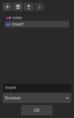
Repeat this operation using the button in the Group Output node this time. The dialog looks the same as the dialog used to edit the input ports.
Now, add a ColorOp node between the input and output nodes. Set its mode to
Difference and connect the input color to the a input of the
ColorOp node. Connect the inverted boolean parameter to the b input
of the ColorOp node. The boolean is automatically converted to a color (pure
black for false, pure white for true). Finally, connect the output of
the ColorOp node to the output node.

Once you're done editing the group's contents, you can go back to the main view using the button on the right in the toolbar:

You can rename a group by clicking on the VisualShaderGroup resource that is part of the Group node:

This will open the VisualShaderGroup node resource for editing in the inspector, where the group name can be changed:
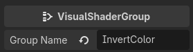
As a convention, group names should follow the PascalCase naming convention to match the built-in nodes, although this is not strictly required.
You can adjust the node parameters like any other visual shader node. For this
example, we'll use a red color ((1.0, 0.0, 0.0, 1.0)) and set the invert
parameter to true:

In this example, since we've connected the output of the group to the Albedo built-in,
we'll get a cyan-colored box as the red color inverted is cyan:

If we disable the invert parameter, the box will be red:

式ノード(Expression Node)
Expression ノードを使用すると、ビジュアルシェーダー内にGodot Shading Language(GLSLのような)式を記述できます。ノードには、必要な量の入力ポートと出力ポートを追加するボタンがあり、サイズを変更できます。各ポートの名前とタイプを設定することもできます。入力した式は、すぐにマテリアルに適用されます(フォーカスが式テキストボックスを離れると)。解析エラーまたはコンパイルエラーは、[出力]タブに出力されます。出力はデフォルトでゼロ値に初期化されます。このノードは[Special]タブの下にあり、すべてのシェーダーモードで使用できます。
このノードの可能性はほとんど無限です。複雑な手順を記述し、ループ、discard キーワード、拡張タイプなどのテキストベースのシェーダーのすべての機能を使用できます。次に例を示します:

Reroute node
The Reroute node is used purely for organizational purposes. In a complicated
shader with many nodes you may find that the paths between nodes can make
things hard to read. Reroute, as its name suggests, allows you to adjust the path
between nodes to make things easier to read. You can even have multiple reroute
nodes for a single path, which can be used to make right angles.

To move a reroute node move your mouse cursor above it, and grab the handle that appears.

フレネルノード
The Fresnel node is designed to accept normal and view vectors and produces
a scalar which is the saturated dot product between them. Additionally, you can
set up the inversion and the power of equation. The Fresnel node is great for
adding a rim-like lighting effect to objects.

ブール型ノード
Boolean ノードは Scalar または Vector に変換して 0 または 1 および '0, 0, 0) または (1, 1, 1, ) を表すことができます。このプロパティを使用すると、一部のエフェクトパーツをワンクリックで有効または無効にできます。

ifノード
The If node allows you to set up a vector which will be returned the result
of the comparison between a and b. There are three vectors which can be
returned: a == b (in that case the tolerance parameter is provided as a
comparison threshold – by default it is equal to the minimal value, i.e.
0.00001), a > b and a < b.

スイッチノード(Switch node)
The Switch node returns a vector if the boolean condition is true or
false. Boolean was introduced above. If you want to convert a vector
to a true boolean, all components of the vector should be non-zero.

Mesh Emitter
The Mesh Emitter node is used for emitting particles from mesh vertices. This is
only available for shaders that are in Particles mode.
Keep in mind that not all 3D objects are mesh files. A glTF file can't be dragged and dropped into the graph. However, you can create an inherited scene from it, save the mesh in that scene as its own file, and use that.

You can also drag and drop obj files into the graph editor to add the node for that specific mesh, other mesh files will not work for this.