2D 中的自訂繪圖
前言
Godot 內建了用於繪製精靈、Polygon、多邊形、粒子、文字等各種常見遊戲開發場景的節點。不過,如果你需要做一些標準節點無法覆蓋的特殊需求,可以讓任何 2D 節點(例如 Control 或 Node2D 衍生節點)用自訂繪圖指令直接在畫面上繪製。
2D 節點中的自訂繪製*非常*有用。下面是一些用例:
繪製現有節點型別無法完成的形狀或邏輯,例如帶有軌跡或特殊動態多邊形的圖像。
繪製大量簡單物件,例如 2D 遊戲用的格線或棋盤。自訂繪圖可以避免使用大量節點帶來的額外負擔,有機會降低記憶體用量並提升效能。
製作自訂的 UI 控制項,以滿足很多可用的控制項之外的特別需求。
繪製
將腳本新增到任何 CanvasItem 衍生節點(例如 Control 或 Node2D)上。然後覆寫 _draw() 方法。
extends Node2D

func _draw():
    pass  # Your draw commands here.
using Godot;

public partial class MyNode2D : Node2D
{
    public override void _Draw()
    {
        // Your draw commands here.
    }
}
繪圖指令的詳細說明可參見 CanvasItem 類別說明文件。這類指令非常多,下面範例會介紹其中幾個常用的。
更新
_draw 方法只會被呼叫一次,之後繪圖指令會被快取起來,所以不需要再重複呼叫。
如果變數或狀態改變後需要重繪,只要在該節點呼叫 CanvasItem.queue_redraw,就會觸發新的 _draw() 呼叫。
以下是一個稍微複雜一點的範例,我們有一個可以隨時修改的貼圖變數,並且透過 setter,在貼圖變更時強制重繪:
extends Node2D

@export var texture : Texture2D:
    set(value):
        texture = value
        queue_redraw()

func _draw():
    draw_texture(texture, Vector2())
using Godot;

public partial class MyNode2D : Node2D
{
    private Texture2D _texture;

    [Export]
    public Texture2D Texture
    {
        get
        {
            return _texture;
        }

        set
        {
            _texture = value;
            QueueRedraw();
        }
    }

    public override void _Draw()
    {
        DrawTexture(_texture, new Vector2());
    }
}
你可以在編輯器中將 FileSystem 分頁下的預設 icon.svg 拖曳到 Inspector 分頁的 Texture 屬性,來測試這段程式。當上面的腳本正在執行時,只要變更 Texture 屬性的值,貼圖也會隨之自動更新。
有時我們可能需要每一禎都重繪。這時可以在 _process 方法裡呼叫 queue_redraw,像這樣:
extends Node2D

func _draw():
    pass  # Your draw commands here.

func _process(_delta):
    queue_redraw()
using Godot;

public partial class MyNode2D : Node2D
{
    public override void _Draw()
    {
        // Your draw commands here.
    }

    public override void _Process(double delta)
    {
        QueueRedraw();
    }
}
座標與線寬對齊
繪圖 API 使用的是 CanvasItem 的座標系統,不一定是像素座標。也就是說,_draw() 用的是應用過 CanvasItem 轉換後的座標空間。此外,你還可以用 draw_set_transform 或 draw_set_transform_matrix 再加上自訂轉換。
使用 draw_line 時,應注意線寬。如果線寬為奇數,起點和終點座標應加上 0.5,才能讓線條置中,如下圖所示。
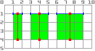
func _draw():
    draw_line(Vector2(1.5, 1.0), Vector2(1.5, 4.0), Color.GREEN, 1.0)
    draw_line(Vector2(4.0, 1.0), Vector2(4.0, 4.0), Color.GREEN, 2.0)
    draw_line(Vector2(7.5, 1.0), Vector2(7.5, 4.0), Color.GREEN, 3.0)
public override void _Draw()
{
    DrawLine(new Vector2(1.5f, 1.0f), new Vector2(1.5f, 4.0f), Colors.Green, 1.0f);
    DrawLine(new Vector2(4.0f, 1.0f), new Vector2(4.0f, 4.0f), Colors.Green, 2.0f);
    DrawLine(new Vector2(7.5f, 1.0f), new Vector2(7.5f, 4.0f), Colors.Green, 3.0f);
}
同理,對 draw_rect 方法(filled = false)也適用。
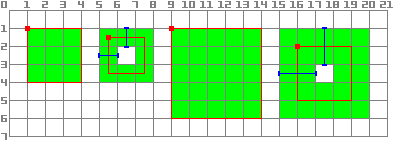
func _draw():
    draw_rect(Rect2(1.0, 1.0, 3.0, 3.0), Color.GREEN)
    draw_rect(Rect2(5.5, 1.5, 2.0, 2.0), Color.GREEN, false, 1.0)
    draw_rect(Rect2(9.0, 1.0, 5.0, 5.0), Color.GREEN)
    draw_rect(Rect2(16.0, 2.0, 3.0, 3.0), Color.GREEN, false, 2.0)
public override void _Draw()
{
    DrawRect(new Rect2(1.0f, 1.0f, 3.0f, 3.0f), Colors.Green);
    DrawRect(new Rect2(5.5f, 1.5f, 2.0f, 2.0f), Colors.Green, false, 1.0f);
    DrawRect(new Rect2(9.0f, 1.0f, 5.0f, 5.0f), Colors.Green);
    DrawRect(new Rect2(16.0f, 2.0f, 3.0f, 3.0f), Colors.Green, false, 2.0f);
}
抗鋸齒繪圖
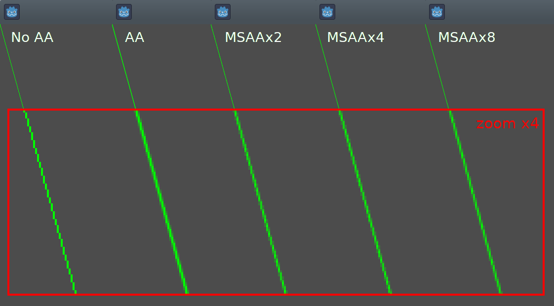
Godot在 draw_line 中提供方法參數來啟用抗鋸齒功能,但並非所有自訂繪圖方法都提供這個 抗鋸齒(antialiased) 參數。
對於不提供 抗鋸齒(antialiased) 參數的自訂繪圖方法,你可以啟用 2D MSAA,這會影響整個視口的算繪。這個功能(2D MSAA)提供了高品質的抗鋸齒,但性能成本更高,而且只適用於特定元素。參見 2D 抗鋸齒 以瞭解更多資訊。
下圖比較了最小寬度(width=-1)的線條在 antialiased=false、antialiased=true,以及啟用 2D MSAA 2x、4x、8x(antialiased=false)下的效果。
工具
有時你也會希望在編輯器中運行節點時自訂繪圖,這可以用來做功能或行為的預覽與視覺化。
你可以在 GDScript 和 C# 中使用 tool annotation 來達成這個效果。更多資訊請參考下方 範例 以及 在編輯器中執行程式碼。
範例 1:繪製自訂形狀
現在我們會用 Godot 的自訂繪圖功能,畫出 Godot 內建函式無法直接繪製的東西。我們將用程式碼,純粹用繪圖指令重現 Godot 標誌。
你需要自行寫一個函式來完成這個繪圖。
備註
以下教學會使用固定座標集,這在高解析度螢幕(大於 1080p)下可能會顯得太小。如果你遇到這種情況,可以在專案設定的 Display > Window > Stretch > Scale 中調高視窗縮放比例(2 或 4 通常效果不錯),以因應高解析度顯示。
繪製自訂多邊形
雖然有專門用來繪製自訂多邊形的節點(Polygon2D),但這裡我們只用較低階的繪圖函式,將所有形狀畫在同一個節點上,這樣之後也方便擴充出更複雜的圖形。
首先,我們要定義一組點(X 和 Y 座標),作為這個形狀的基礎:
extends Node2D

var coords_head : Array = [
    [ 22.952, 83.271 ],  [ 28.385, 98.623 ],
    [ 53.168, 107.647 ], [ 72.998, 107.647 ],
    [ 99.546, 98.623 ],  [ 105.048, 83.271 ],
    [ 105.029, 55.237 ], [ 110.740, 47.082 ],
    [ 102.364, 36.104 ], [ 94.050, 40.940 ],
    [ 85.189, 34.445 ],  [ 85.963, 24.194 ],
    [ 73.507, 19.930 ],  [ 68.883, 28.936 ],
    [ 59.118, 28.936 ],  [ 54.494, 19.930 ],
    [ 42.039, 24.194 ],  [ 42.814, 34.445 ],
    [ 33.951, 40.940 ],  [ 25.637, 36.104 ],
    [ 17.262, 47.082 ],  [ 22.973, 55.237 ]
]
using Godot;

public partial class MyNode2D : Node2D
{
    private float[,] _coordsHead =
    {
        { 22.952f, 83.271f },  { 28.385f, 98.623f },
        { 53.168f, 107.647f }, { 72.998f, 107.647f },
        { 99.546f, 98.623f },  { 105.048f, 83.271f },
        { 105.029f, 55.237f }, { 110.740f, 47.082f },
        { 102.364f, 36.104f }, { 94.050f, 40.940f },
        { 85.189f, 34.445f },  { 85.963f, 24.194f },
        { 73.507f, 19.930f },  { 68.883f, 28.936f },
        { 59.118f, 28.936f },  { 54.494f, 19.930f },
        { 42.039f, 24.194f },  { 42.814f, 34.445f },
        { 33.951f, 40.940f },  { 25.637f, 36.104f },
        { 17.262f, 47.082f },  { 22.973f, 55.237f }
    };
}
這種格式雖然精簡,但 Godot 並不直接支援用來繪製多邊形。在不同情境下,你可能需要從檔案讀取這些座標,或在執行時動態計算,因此可能要進行額外的轉換。
為了將這些座標轉換成 Godot 可用的格式,我們會寫一個新的方法 float_array_to_Vector2Array()。接著覆寫 _ready() 函式(Godot 會在執行開始時只呼叫一次),將這些座標載入變數:
var head : PackedVector2Array

func float_array_to_Vector2Array(coords : Array) -> PackedVector2Array:
    # Convert the array of floats into a PackedVector2Array.
    var array : PackedVector2Array = []
    for coord in coords:
        array.append(Vector2(coord[0], coord[1]))
    return array

func _ready():
    head = float_array_to_Vector2Array(coords_head);
private Vector2[] _head;

private Vector2[] FloatArrayToVector2Array(float[,] coords)
{
    // Convert the array of floats into an array of Vector2.
    int size = coords.GetUpperBound(0);
    Vector2[] array = new Vector2[size + 1];
    for (int i = 0; i <= size; i++)
    {
        array[i] = new Vector2(coords[i, 0], coords[i, 1]);
    }
    return array;
}

public override void _Ready()
{
    _head = FloatArrayToVector2Array(_coordsHead);
}
最後,我們會使用 draw_polygon 方法來繪製這個形狀,傳入點的陣列(Vector2 格式)和顏色,如下所示:
func _draw():
    # We are going to paint with this color.
    var godot_blue : Color = Color("478cbf")
    # We pass the PackedVector2Array to draw the shape.
    draw_polygon(head, [ godot_blue ])
public override void _Draw()
{
    // We are going to paint with this color.
    Color godotBlue = new Color("478cbf");
    // We pass the array of Vector2 to draw the shape.
    DrawPolygon(_head, [godotBlue]);
}
執行時你應該會看到類似這樣的畫面:
請注意,Logo 下半部看起來呈現分段狀,這是因為這部分只用了少量點來定義。若想要模擬平滑曲線,可以在陣列中增加更多點,或用數學函式來插值產生曲線,直接在程式碼中建立平滑形狀(詳見 範例 2)。
多邊形會自動將最後一個點與第一個點連接,形成封閉形狀。
繪製連續線段
繪製一串不封閉成多邊形的連續線段,其方式與前述方法相似。我們會用連續線段來繪製 Godot 標誌上的嘴巴。
首先,定義構成嘴巴形狀的座標列表,如下所示:
var coords_mouth = [
    [ 22.817, 81.100 ], [ 38.522, 82.740 ],
    [ 39.001, 90.887 ], [ 54.465, 92.204 ],
    [ 55.641, 84.260 ], [ 72.418, 84.177 ],
    [ 73.629, 92.158 ], [ 88.895, 90.923 ],
    [ 89.556, 82.673 ], [ 105.005, 81.100 ]
]
private float[,] _coordsMouth =
{
    { 22.817f, 81.100f }, { 38.522f, 82.740f },
    { 39.001f, 90.887f }, { 54.465f, 92.204f },
    { 55.641f, 84.260f }, { 72.418f, 84.177f },
    { 73.629f, 92.158f }, { 88.895f, 90.923f },
    { 89.556f, 82.673f }, { 105.005f, 81.100f }
};
我們會將這些座標載入一個變數,並另外定義一個可調整的線寬變數:
var mouth : PackedVector2Array
var _mouth_width : float = 4.4

func _ready():
    head = float_array_to_Vector2Array(coords_head);
    mouth = float_array_to_Vector2Array(coords_mouth);
private Vector2[] _mouth;
private float _mouthWidth = 4.4f;

public override void _Ready()
{
    _head = FloatArrayToVector2Array(_coordsHead);
    _mouth = FloatArrayToVector2Array(_coordsMouth);
}
最後,我們用 draw_polyline 方法來真正畫出這條線,如下:
func _draw():
    # We will use white to draw the line.
    var white : Color = Color.WHITE
    var godot_blue : Color = Color("478cbf")

    draw_polygon(head, [ godot_blue ])

    # We draw the while line on top of the previous shape.
    draw_polyline(mouth, white, _mouth_width)
public override void _Draw()
{
    // We will use white to draw the line.
    Color white = Colors.White;
    Color godotBlue = new Color("478cbf");

    DrawPolygon(_head, [godotBlue]);

    // We draw the while line on top of the previous shape.
    DrawPolyline(_mouth, white, _mouthWidth);
}
你應該會看到以下結果:
和 draw_polygon() 不同的是,polyline 只能為所有點指定一個單一顏色(第二個參數)。這個方法還有兩個額外參數:線寬(預設為最細),以及是否啟用抗鋸齒(預設關閉)。
_draw 的呼叫順序很重要——就像場景樹中的節點一樣,繪圖會從上到下依序執行,被後畫的圖形會覆蓋在前面的圖形上。如果兩個圖形重疊,最晚繪製的會蓋住之前的。在這個例子中,我們希望嘴巴畫在頭的上方,所以將其放在後面。
注意,我們可以用不同的方式定義顏色,例如十六進位色碼或預設顏色名稱。更多常數和顏色定義方式請參考 Color 類別。
繪製圓形
要畫出眼睛,我們會額外呼叫 4 次繪圖函式,分別以不同的大小、顏色與位置來畫出眼睛的形狀。
要畫圓形,可以用 draw_circle 方法,指定圓心的位置(以 Vector2 表示)、半徑與顏色:
func _draw():
    var white : Color = Color.WHITE
    var godot_blue : Color = Color("478cbf")
    var grey : Color = Color("414042")

    draw_polygon(head, [ godot_blue ])
    draw_polyline(mouth, white, _mouth_width)

    # Four circles for the 2 eyes: 2 white, 2 grey.
    draw_circle(Vector2(42.479, 65.4825), 9.3905, white)
    draw_circle(Vector2(85.524, 65.4825), 9.3905, white)
    draw_circle(Vector2(43.423, 65.92), 6.246, grey)
    draw_circle(Vector2(84.626, 66.008), 6.246, grey)
public override void _Draw()
{
    Color white = Colors.White;
    Color godotBlue = new Color("478cbf");
    Color grey = new Color("414042");

    DrawPolygon(_head, [godotBlue]);
    DrawPolyline(_mouth, white, _mouthWidth);

    // Four circles for the 2 eyes: 2 white, 2 grey.
    DrawCircle(new Vector2(42.479f, 65.4825f), 9.3905f, white);
    DrawCircle(new Vector2(85.524f, 65.4825f), 9.3905f, white);
    DrawCircle(new Vector2(43.423f, 65.92f), 6.246f, grey);
    DrawCircle(new Vector2(84.626f, 66.008f), 6.246f, grey);
}
執行時你應該會看到這樣的畫面:
若要繪製不填滿的圓弧(由特定角度決定的圓的一部分),可以用 draw_arc 方法。
繪製線條
最後要繪製鼻子這個形狀時,我們會用一條線來近似。
你可以用 draw_line 方法來畫一段線段,只需提供起點和終點座標,如下:
func _draw():
    var white : Color = Color.WHITE
    var godot_blue : Color = Color("478cbf")
    var grey : Color = Color("414042")

    draw_polygon(head, [ godot_blue ])
    draw_polyline(mouth, white, _mouth_width)
    draw_circle(Vector2(42.479, 65.4825), 9.3905, white)
    draw_circle(Vector2(85.524, 65.4825), 9.3905, white)
    draw_circle(Vector2(43.423, 65.92), 6.246, grey)
    draw_circle(Vector2(84.626, 66.008), 6.246, grey)

    # Draw a short but thick white vertical line for the nose.
    draw_line(Vector2(64.273, 60.564), Vector2(64.273, 74.349), white, 5.8)
public override void _Draw()
{
    Color white = Colors.White;
    Color godotBlue = new Color("478cbf");
    Color grey = new Color("414042");

    DrawPolygon(_head, [godotBlue]);
    DrawPolyline(_mouth, white, _mouthWidth);
    DrawCircle(new Vector2(42.479f, 65.4825f), 9.3905f, white);
    DrawCircle(new Vector2(85.524f, 65.4825f), 9.3905f, white);
    DrawCircle(new Vector2(43.423f, 65.92f), 6.246f, grey);
    DrawCircle(new Vector2(84.626f, 66.008f), 6.246f, grey);

    // Draw a short but thick white vertical line for the nose.
    DrawLine(new Vector2(64.273f, 60.564f), new Vector2(64.273f, 74.349f),
             white, 5.8f);
}
現在你應該能在螢幕上看到下列形狀:
注意,如果要同時畫多條不連接的線段,可以用 draw_multiline 方法一次畫出所有線段,這樣效能會更好。
繪製文字
雖然最常見的文字顯示方法是使用 Label 節點,但底層的 _draw 函式也能讓你在自訂節點繪圖中加入文字。我們會用這個方法在機器人頭下方加上「GODOT」字樣。
這裡我們會用 draw_string 方法來達成:
var default_font : Font = ThemeDB.fallback_font;

func _draw():
    var white : Color = Color.WHITE
    var godot_blue : Color = Color("478cbf")
    var grey : Color = Color("414042")

    draw_polygon(head, [ godot_blue ])
    draw_polyline(mouth, white, _mouth_width)
    draw_circle(Vector2(42.479, 65.4825), 9.3905, white)
    draw_circle(Vector2(85.524, 65.4825), 9.3905, white)
    draw_circle(Vector2(43.423, 65.92), 6.246, grey)
    draw_circle(Vector2(84.626, 66.008), 6.246, grey)
    draw_line(Vector2(64.273, 60.564), Vector2(64.273, 74.349), white, 5.8)

    # Draw GODOT text below the logo with the default font, size 22.
    draw_string(default_font, Vector2(20, 130), "GODOT",
                HORIZONTAL_ALIGNMENT_CENTER, 90, 22)
private Font _defaultFont = ThemeDB.FallbackFont;

public override void _Draw()
{
    Color white = Colors.White;
    Color godotBlue = new Color("478cbf");
    Color grey = new Color("414042");

    DrawPolygon(_head, [godotBlue]);
    DrawPolyline(_mouth, white, _mouthWidth);
    DrawCircle(new Vector2(42.479f, 65.4825f), 9.3905f, white);
    DrawCircle(new Vector2(85.524f, 65.4825f), 9.3905f, white);
    DrawCircle(new Vector2(43.423f, 65.92f), 6.246f, grey);
    DrawCircle(new Vector2(84.626f, 66.008f), 6.246f, grey);
    DrawLine(new Vector2(64.273f, 60.564f), new Vector2(64.273f, 74.349f),
             white, 5.8f);

    // Draw GODOT text below the logo with the default font, size 22.
    DrawString(_defaultFont, new Vector2(20f, 130f), "GODOT",
               HorizontalAlignment.Center, 90, 22);
}
這裡我們先將預設主題字型載入到 defaultFont 變數(你也可以用自訂字型),接著傳入參數:字型、位置、文字內容、水平對齊方式、寬度,以及字體大小。
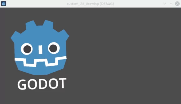
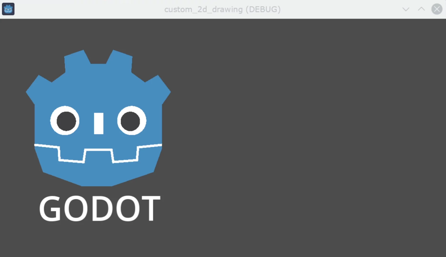
你應該會在螢幕上看到下列畫面:
更多文字相關的參數與方法,請參考 CanvasItem 類別說明文件。
在編輯時顯示繪圖
目前為止的程式碼雖然能在執行時畫出 logo,但在編輯器的「2D 檢視」中並不會顯示。有些情況下,你也會希望自訂的 Node2D 或控制項能在編輯器中顯示,方便定位和調整大小,就像其他節點一樣。
若要讓 logo 直接在編輯器中顯示(不執行時也能看見),你可以加上 @tool 註解,讓自訂節點的繪圖也會在編輯時出現,例如:
@tool
extends Node2D
using Godot;

[Tool]
public partial class MyNode2D : Node2D
在你第一次新增或移除 @tool 註解後,需要儲存場景,並(C# 專案)重新編譯,再從選單選取「場景 > 重新載入已儲存場景」刷新 2D 檢視,這樣才能看到節點的最新繪圖。
動畫
如果想在執行時讓自訂形狀變化,可以在執行期間修改呼叫的方法或其參數,或是套用變換。
例如,若想讓剛剛設計的自訂形狀旋轉,可以在 _ready 和 _process 方法中加上以下變數與程式碼:
extends Node2D

@export var rotation_speed : float = 1  # In radians per second.

func _ready():
    rotation = 0
    ...

func _process(delta: float):
    rotation -= rotation_speed * delta
[Export]
public float RotationSpeed { get; set; } = 1.0f;  // In radians per second.

public override void _Ready()
{
    Rotation = 0;
    ...
}

public override void _Process(double delta)
{
    Rotation -= RotationSpeed * (float)delta;
}
上面的程式碼有個問題:由於我們的點是從左上角 (0, 0) 開始,一路往右下建立,因此旋轉時會以左上角為中心。單純改變節點的位置變換沒辦法解決,因為旋轉變換會先套用。
雖然我們可以將所有點的座標重寫成以 (0, 0) 為中心(包含負座標),但這樣會相當麻煩。
一個解決方式是用較低階的 draw_set_transform 方法,先把所有點在 CanvasItem 的座標空間中平移,把中心移到你想要的軸心,然後再用節點的平移將它移回原本位置(可在編輯器或程式中設定),像這樣:
func _ready():
    rotation = 0
    position = Vector2(60, 60)
    ...

func _draw():
    draw_set_transform(Vector2(-60, -60))
    ...
public override void _Ready()
{
    Rotation = 0;
    Position = new Vector2(60, 60);
    ...
}

public override void _Draw()
{
    DrawSetTransform(new Vector2(-60.0f, -60.0f));
    ...
}
這樣結果就會繞著 (60, 60) 為中心旋轉:
如果想讓 _draw() 中的某個屬性產生動畫,要記得呼叫 queue_redraw() 強制重繪,否則畫面不會即時更新。
例如,我們可以改變機器人嘴巴的線段寬度,讓它看起來像是在張嘴和閉嘴,讓寬度隨著正弦波(sin)變化:
var _mouth_width : float = 4.4
var _max_width : float = 7
var _time : float = 0

func _process(delta : float):
    _time += delta
    _mouth_width = abs(sin(_time) * _max_width)
    queue_redraw()

func _draw():
    ...
    draw_polyline(mouth, white, _mouth_width)
    ...
private float _mouthWidth = 4.4f;
private float _maxWidth = 7f;
private float _time = 0f;

public override void _Process(double delta)
{
    _time += (float)delta;
    _mouthWidth = Mathf.Abs(Mathf.Sin(_time) * _maxWidth);
    QueueRedraw();
}

public override void _Draw()
{
    ...
    DrawPolyline(_mouth, white, _mouthWidth);
    ...
}
執行時大致會長這樣:
請注意,_mouth_width 和其他自訂屬性一樣,也可以用更高階的方式(例如 Tween 或 AnimationPlayer 節點)來製作動畫。唯一的差別是,你必須呼叫 queue_redraw() 才會讓螢幕及時顯示動畫效果。
範例 2:繪製動態線段
前面的範例讓你學會了如何用自訂形狀和動畫來繪製和修改節點。這種做法有一些優點,例如可用精確座標與向量繪圖(不是用點陣圖),因此在螢幕縮放時會維持品質。有時候也可以用更高階的元件組合出類似效果,例如用 Sprite2D、AnimatedSprite2D 載入 SVG 資源(SVG 也是向量圖),搭配 AnimationPlayer 節點。
有些情況下,執行前並不知道圖形的最終樣貌,因此無法預先準備。這裡我們會示範如何畫出一條座標未知、會根據使用者輸入動態變化的線段。
繪製兩點之間的直線
假設我們要畫一條連接兩點的直線,第一個點固定在左上角 (0, 0),第二個點則由螢幕上的游標位置決定。
可以用下列方式畫出這兩點之間的動態直線:
extends Node2D

var point1 : Vector2 = Vector2(0, 0)
var width : int = 10
var color : Color = Color.GREEN

var _point2 : Vector2

func _process(_delta):
    var mouse_position = get_viewport().get_mouse_position()
    if mouse_position != _point2:
        _point2 = mouse_position
        queue_redraw()

func _draw():
    draw_line(point1, _point2, color, width)
using Godot;
using System;

public partial class MyNode2DLine : Node2D
{
    public Vector2 Point1 { get; set; } = new Vector2(0f, 0f);
    public int Width { get; set; } = 10;
    public Color Color { get; set; } = Colors.Green;

    private Vector2 _point2;

    public override void _Process(double delta)
    {
        Vector2 mousePosition = GetViewport().GetMousePosition();
        if (mousePosition != _point2)
        {
            _point2 = mousePosition;
            QueueRedraw();
        }
    }

    public override void _Draw()
    {
        DrawLine(Point1, _point2, Color, Width);
    }
}
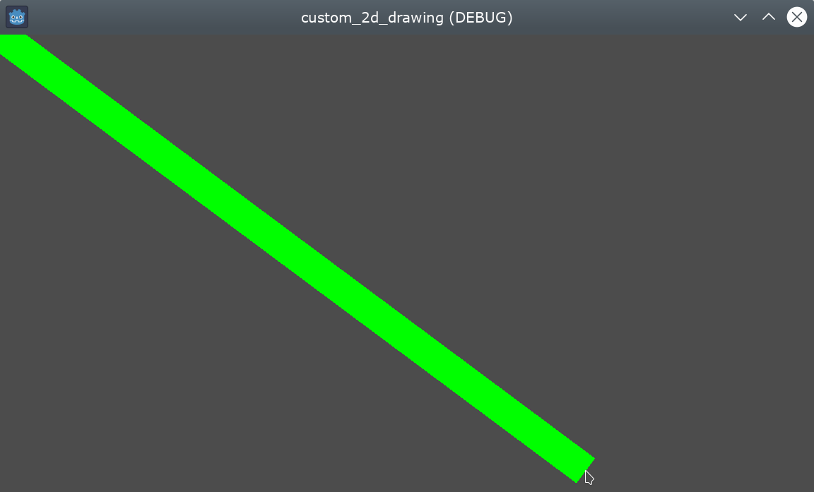
這個範例中,我們每一禎都用 get_mouse_position 取得滑鼠在預設視口中的位置。如果位置自上次繪製以來有變化(這樣可以避免每一禎都重繪),就安排重繪。_draw() 方法只會畫一條線:從左上角到滑鼠位置的綠色線段,寬度為 10 像素。
線段的寬度、顏色和起點位置都可以用對應的屬性來設定。
執行時效果如下:
繪製兩點之間的圓弧
上面的範例可以運作,不過有時候你可能想用直線以外的形狀或方式連接這兩個點。
這次我們試著在兩點間畫出一段圓弧(圓的一部分)。
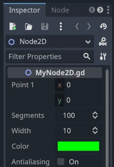
如果將線的起點、分段數、寬度、顏色與抗鋸齒等屬性導出(export),就可以直接在編輯器屬性面板輕鬆調整這些參數:
extends Node2D

@export var point1 : Vector2 = Vector2(0, 0)
@export_range(1, 1000) var segments : int = 100
@export var width : int = 10
@export var color : Color = Color.GREEN
@export var antialiasing : bool = false

var _point2 : Vector2
using Godot;
using System;

public partial class MyNode2DLine : Node2D
{
    [Export]
    public Vector2 Point1 { get; set; } = new Vector2(0f, 0f);
    [Export]
    public float Length { get; set; } = 350f;
    [Export(PropertyHint.Range, "1,1000,")]
    public int Segments { get; set; } = 100;
    [Export]
    public int Width { get; set; } = 10;
    [Export]
    public Color Color { get; set; } = Colors.Green;
    [Export]
    public bool AntiAliasing { get; set; } = false;

    private Vector2 _point2;
}
畫圓弧時,可以用 draw_arc 方法。能通過兩點的圓弧有很多種,這裡我們選擇將圓心設在這兩點的中點,畫出一段半圓。
計算這段圓弧會比直線稍微複雜一點:
func _draw():
    # Average points to get center.
    var center : Vector2 = Vector2((_point2.x + point1.x) / 2,
                                   (_point2.y + point1.y) / 2)
    # Calculate the rest of the arc parameters.
    var radius : float = point1.distance_to(_point2) / 2
    var start_angle : float = (_point2 - point1).angle()
    var end_angle : float = (point1 - _point2).angle()
    if end_angle < 0:  # end_angle is likely negative, normalize it.
        end_angle += TAU

    # Finally, draw the arc.
    draw_arc(center, radius, start_angle, end_angle, segments, color,
             width, antialiasing)
public override void _Draw()
{
    // Average points to get center.
    Vector2 center = new Vector2((_point2.X + Point1.X) / 2.0f,
                                    (_point2.Y + Point1.Y) / 2.0f);
    // Calculate the rest of the arc parameters.
    float radius = Point1.DistanceTo(_point2) / 2.0f;
    float startAngle = (_point2 - Point1).Angle();
    float endAngle = (Point1 - _point2).Angle();
    if (endAngle < 0.0f)  // endAngle is likely negative, normalize it.
    {
        endAngle += Mathf.Tau;
    }

    // Finally, draw the arc.
    DrawArc(center, radius, startAngle, endAngle, Segments, Color,
            Width, AntiAliasing);
}
這裡半圓的圓心會設在兩點的中點,半徑是兩點距離的一半。起始角度和結束角度分別是 point1 到 point2 或從 point2 到 point1 的向量角度。注意我們要把 end_angle 轉成正值,否則如果 end_angle 小於 start_angle,圓弧會逆時針繪製(這不是我們想要的,因為這樣會畫在上方)。
結果應該會如下圖,圓弧往下並連接兩點:
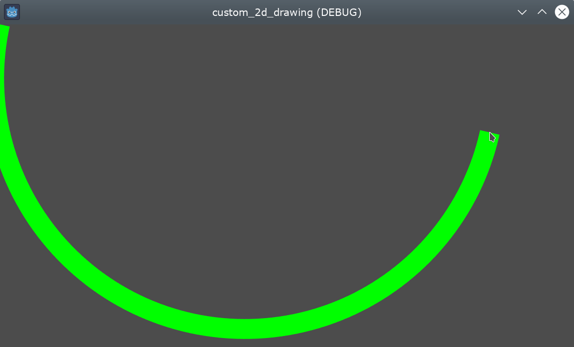
你可以隨意在屬性面板調整這些參數,獲得不同效果:改變顏色、線寬、抗鋸齒或增加分段數讓曲線更平滑(但會消耗更多效能)。