Attention: Here be dragons
This is the latest
(unstable) version of this documentation, which may document features
not available in or compatible with released stable versions of Godot.
Checking the stable version of the documentation...
Использование SubViewport в качестве текстуры
Введение
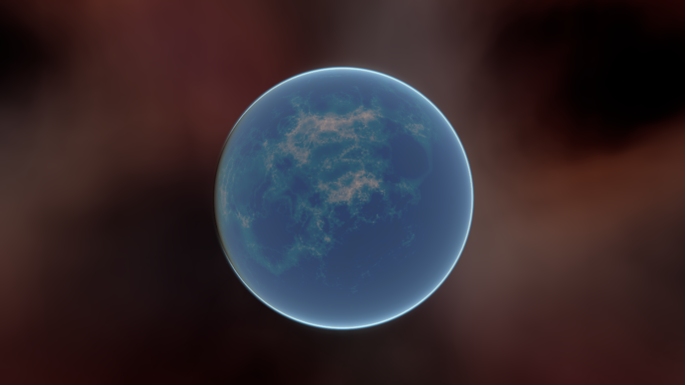
В этом уроке вы познакомитесь с использованием SubViewport в качестве текстуры, которую можно применять к 3D-объектам. Для этого мы покажем вам процесс создания процедурной планеты, подобной показанной ниже:
Примечание
В этом руководстве не рассматривается, как кодировать динамическую атмосферу, подобную той, что есть на этой планете.
В этом руководстве предполагается, что вы знакомы с настройкой базовой сцены, включая: Camera3D, light source, MeshInstance3D с Primitive Mesh и применением StandardMaterial3D к сетке. Основное внимание будет уделено использованию SubViewport для динамического создания текстур, которые можно применять к сетке.
В этом уроке мы рассмотрим следующие темы:
Как использовать SubViewport в качестве текстуры рендеринга
Наложение текстуры на сферу с помощью равнопрямоугольного отображения
Методы фрагментного шейдера для процедурных планет
Установка карты Roughness (шероховатости) из Viewport Texture
Настраиваем сцену
Создайте новую сцену и добавьте следующие узлы точно так, как показано ниже.

Перейдите в MeshInstance3D и создайте сетку SphereMesh
Настройка SubViewport
Щёлкните по узлу SubViewport и задайте ему размер (1024, 512). SubViewport может быть любого размера, при условии, что его ширина вдвое больше высоты. Ширина должна быть вдвое больше высоты, чтобы изображение точно отображалось на сфере, поскольку мы будем использовать равнопромежуточную проекцию, но подробнее об этом позже.
Затем отключите 3D. Мы будем использовать ColorRect для рендеринга поверхности, поэтому 3D нам тоже не нужно.

Выберите ColorRect и в инспекторе установите для якорей значение Полный прямоугольник. Это гарантирует, что ColorRect займет весь SubViewport.

Затем мы добавляем Shader Material к ColorRect (ColorRect > CanvasItem > Material > Material > New ShaderMaterial).
Примечание
Для этого урока рекомендуется иметь базовые знания о шейдерах. Однако, даже если вы новичок в шейдерах, весь код будет предоставлен, так что у вас не возникнет проблем с пониманием.
Нажмите кнопку выпадающего меню для материала шейдера и выберите / Edit. Далее выберите Shader > New Shader. Дайте ему имя и нажмите "Create". Щелкните шейдер в инспекторе, чтобы открыть редактор шейдеров. Удалите код по умолчанию и добавьте следующее:
shader_type canvas_item;

void fragment() {
    COLOR = vec4(UV.x, UV.y, 0.5, 1.0);
}
cохраните код шейдера, и в инспекторе вы увидите, что приведенный выше код визуализирует градиент, подобный показанному ниже.
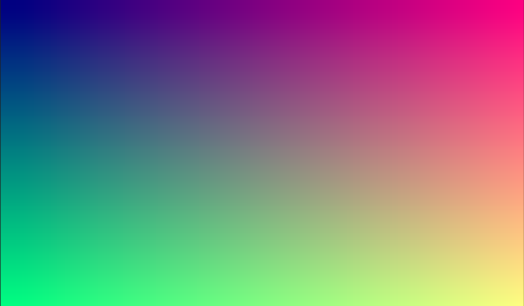
Теперь у нас есть основы SubViewport, в который мы выполняем рендеринг, и у нас есть уникальное изображение, которое мы можем применить к сфере.
Нанесение текстуры
Теперь перейдите в MeshInstance3D и добавьте к нему StandardMaterial3D. Специальный Shader Material не нужен (хотя для более продвинутых эффектов, таких как атмосфера в примере выше, это было бы неплохой идеей).
MeshInstance3D > GeometryInstance > Geometry > Material Override > New StandardMaterial3D
Затем щелкните раскрывающийся список StandardMaterial3D и нажмите "Edit"
Перейдите в раздел "Resource" и установите флажок Local to scene. Затем перейдите в раздел "Albedo" и нажмите рядом со свойством "Texture", чтобы добавить текстуру альбедо. Здесь мы применим созданную нами текстуру. Выберите "New ViewportTexture"

Щелкните по ViewportTexture, который вы только что создали в инспекторе, затем нажмите "Assign". Затем в появившемся меню выберите Viewport, в котором мы ранее выполнили рендеринг.

Теперь ваша сфера должна быть окрашена в цвета, которые мы передали в Viewport.

Заметили некрасивый шов, который образуется там, где текстура оборачивается вокруг? Это потому, что мы выбираем цвет на основе UV-координат, а UV-координаты не оборачиваются вокруг текстуры. Это классическая проблема при проекции двумерных карт. Разработчики игр часто имеют двумерную карту, которую они хотят спроецировать на сферу, но когда она оборачивается вокруг, получаются большие швы. Существует элегантный обходной путь решения этой проблемы, который мы проиллюстрируем в следующем разделе.
Создание текстуры планеты
Итак, теперь, когда мы рендерим в наш SubViewport, он чудесным образом отображается на сфере. Но есть некрасивый шов, создаваемый нашими текстурными координатами. Как же нам получить диапазон координат, который будет красиво огибать сферу? Одно из решений — использовать функцию, повторяющуюся в области определения нашей текстуры. sin и cos — две такие функции. Давайте применим их к текстуре и посмотрим, что получится. Замените существующий код цвета в шейдере следующим:
COLOR.xyz = vec3(sin(UV.x * 3.14159 * 4.0) * cos(UV.y * 3.14159 * 4.0) * 0.5 + 0.5);

Недурно. Если присмотреться, можно увидеть, что шов исчез, но вместо него у нас образовалось сжатие полюсов. Это сжатие обусловлено тем, как Godot накладывает текстуры на сферы в своём StandardMaterial3D. Он использует технику проецирования, называемую равнопрямоугольной проекцией, которая переводит сферическую карту в двумерную плоскость.
Примечание
Если вам интересно узнать больше об этой технике, мы перейдём из сферических координат в декартовы. Сферические координаты отображают долготу и широту сферы, а декартовы координаты, по сути, представляют собой вектор из центра сферы в заданную точку.
Для каждого пикселя мы вычислим его трехмерное положение на сфере. Исходя из этого, мы будем использовать 3D-шум для определения значения цвета. Рассчитывая шум в 3D, мы решаем проблему защемления на полюсах. Чтобы понять, почему, представьте, что шум рассчитывается по поверхности сферы, а не по двухмерной плоскости. Когда вы рассчитываете по поверхности сферы, вы никогда не заденете край, а значит, не создадите шов или точку защемления на полюсе. Следующий код преобразует UV в декартовы координаты.
float theta = UV.y * 3.14159;
float phi = UV.x * 3.14159 * 2.0;
vec3 unit = vec3(0.0, 0.0, 0.0);

unit.x = sin(phi) * sin(theta);
unit.y = cos(theta) * -1.0;
unit.z = cos(phi) * sin(theta);
unit = normalize(unit);
А если мы используем unit как выходное значение COLOR, то получим:

Теперь, когда мы можем рассчитать 3D положение поверхности сферы, мы можем использовать 3D шум для создания планеты. Мы будем использовать эту функцию шума непосредственно из Shadertoy:
vec3 hash(vec3 p) {
    p = vec3(dot(p, vec3(127.1, 311.7, 74.7)),
             dot(p, vec3(269.5, 183.3, 246.1)),
             dot(p, vec3(113.5, 271.9, 124.6)));

    return -1.0 + 2.0 * fract(sin(p) * 43758.5453123);
}

float noise(vec3 p) {
  vec3 i = floor(p);
  vec3 f = fract(p);
  vec3 u = f * f * (3.0 - 2.0 * f);

  return mix(mix(mix(dot(hash(i + vec3(0.0, 0.0, 0.0)), f - vec3(0.0, 0.0, 0.0)),
                     dot(hash(i + vec3(1.0, 0.0, 0.0)), f - vec3(1.0, 0.0, 0.0)), u.x),
                 mix(dot(hash(i + vec3(0.0, 1.0, 0.0)), f - vec3(0.0, 1.0, 0.0)),
                     dot(hash(i + vec3(1.0, 1.0, 0.0)), f - vec3(1.0, 1.0, 0.0)), u.x), u.y),
             mix(mix(dot(hash(i + vec3(0.0, 0.0, 1.0)), f - vec3(0.0, 0.0, 1.0)),
                     dot(hash(i + vec3(1.0, 0.0, 1.0)), f - vec3(1.0, 0.0, 1.0)), u.x),
                 mix(dot(hash(i + vec3(0.0, 1.0, 1.0)), f - vec3(0.0, 1.0, 1.0)),
                     dot(hash(i + vec3(1.0, 1.0, 1.0)), f - vec3(1.0, 1.0, 1.0)), u.x), u.y), u.z );
}
Примечание
Все права принадлежат автору, Inigo Quilez. Книга опубликована по лицензии MIT.
Теперь, чтобы использовать noise, добавьте к функции fragment следующее:
float n = noise(unit * 5.0);
COLOR.xyz = vec3(n * 0.5 + 0.5);

Примечание
Чтобы подчеркнуть текстуру, мы устанавливаем материал без затенения.
Теперь вы видите, что шум действительно плавно обволакивает сферу. Хотя это совсем не похоже на обещанную планету. Так что давайте перейдём к чему-нибудь более красочному.
Раскрашиваем планету
Теперь займёмся цветами планеты. Хотя есть много способов сделать это, пока мы остановимся на градиенте между водой и сушей.
Для создания градиента в GLSL мы используем функцию mix. mix принимает два значения для интерполяции и третий аргумент, определяющий степень интерполяции; по сути, она смешивает два значения. В других API эта функция часто называется lerp. Однако lerp обычно зарезервировано для смешивания двух чисел с плавающей точкой; mix может принимать любые значения, будь то числа с плавающей точкой или векторные типы.
COLOR.xyz = mix(vec3(0.05, 0.3, 0.5), vec3(0.9, 0.4, 0.1), n * 0.5 + 0.5);
Первый цвет — синий для океана. Второй — красноватый (потому что всем инопланетным планетам нужен красный ландшафт). И наконец, они смешиваются по формуле n * 0,5 + 0,5. n плавно меняется от -1 до 1. Поэтому мы преобразуем его в диапазон 0-1, ожидаемый mix. Теперь вы видите, что цвета меняются от синего к красному.

Это немного более размыто, чем нам хотелось бы. На планетах обычно наблюдается относительно чёткое разделение суши и моря. Для этого мы заменим последний член на smoothstep(-0.1, 0.0, n). Таким образом, вся строка примет вид:
COLOR.xyz = mix(vec3(0.05, 0.3, 0.5), vec3(0.9, 0.4, 0.1), smoothstep(-0.1, 0.0, n));
Функция smoothstep возвращает 0, если третий аргумент меньше первого, и 1, если третий аргумент больше второго, а также плавно переходит от 0 к 1, если третье число находится между первым и вторым. Таким образом, в этой строке smoothstep возвращает 0, когда n меньше -0.1, и возвращает 1, когда n больше 0.

Еще одна вещь, чтобы сделать это немного более планетарным. Земля не должна быть такой шарообразной; давайте сделаем края немного более грубыми. Трюк, который часто используется в шейдерах для создания грубого рельефа с помощью шума, заключается в наложении друг на друга уровней шума с различными частотами. Мы используем один слой для создания общей шарообразной структуры континентов. Затем другой слой немного разбивает края, затем еще один, и так далее. Мы вычислим n с помощью четырех строк кода шейдера вместо одной. n становится:
float n = noise(unit * 5.0) * 0.5;
n += noise(unit * 10.0) * 0.25;
n += noise(unit * 20.0) * 0.125;
n += noise(unit * 40.0) * 0.0625;
И теперь планета выглядит так:

Создаём океан
И последний штрих, чтобы сделать изображение более похожим на планету. Океан и суша отражают свет по-разному. Поэтому мы хотим, чтобы океан блестел немного ярче, чем суша. Этого можно добиться, передав четвёртое значение в канал альфа нашего выходного ЦВЕТ и используя его как карту Roughness.
COLOR.a = 0.3 + 0.7 * smoothstep(-0.1, 0.0, n);
Эта строка возвращает значение 0.3 для воды и 1.0 для суши. Это означает, что суша будет довольно неровной, а вода — довольно гладкой.
Затем в разделе "Metallic" материала убедитесь, что параметр Metallic установлен на значение 0, а параметр Specular — на значение 1. Это связано с тем, что вода хорошо отражает свет, но не имеет металлического блеска. Эти значения не являются физически точными, но для данной демонстрации их вполне достаточно.
Затем в разделе "Roughness" установите текстуру шероховатости Viewport Texture, указывающую на текстуру нашей планеты SubViewport. Наконец, установите Texture Channel на Alpha. Это предписывает рендереру использовать канал alpha нашего выходного COLOR в качестве значения Roughness.

Вы заметите, что изменений практически нет, за исключением того, что планета больше не отражает небо. Это происходит потому, что по умолчанию при рендеринге с альфа-значением объект отображается как прозрачный поверх фона. А поскольку фон по умолчанию для SubViewport непрозрачен, канал alpha для Viewport Texture равен 1, в результате чего текстура планеты отображается с чуть более тусклыми цветами и значением Roughness (шероховатости), равным 1 везде. Чтобы исправить это, мы переходим к SubViewport и включаем свойство "Transparent Bg (Прозрачный фон)". Поскольку теперь мы рендерим один прозрачный объект поверх другого, нам нужно включить blend_premul_alpha:
render_mode blend_premul_alpha;
Это предварительно умножает цвета на значение alpha, а затем корректно смешивает их. Обычно при наложении одного прозрачного цвета на другой, даже если у фона значение alpha равно 0 (как в данном случае), возникают странные проблемы со смешиванием цветов. Установка blend_premul_alpha решает эту проблему.
Теперь планета должна выглядеть так, как будто она отражает свет от океана, но не от земли. Перемещайте OmniLight3D в сцене, чтобы увидеть эффект отражений от океана.

И вот оно. Процедурная планета, сгенерированная с помощью SubViewport.